Welcome to the Onshape forum! Ask questions and join in the discussions about everything Onshape.
First time visiting? Here are some places to start:- Looking for a certain topic? Check out the categories filter or use Search (upper right).
- Need support? Ask a question to our Community Support category.
- Please submit support tickets for bugs but you can request improvements in the Product Feedback category.
- Be respectful, on topic and if you see a problem, Flag it.
If you would like to contact our Community Manager personally, feel free to send a private message or an email.
Adding Nubs or Ribs to the Inside of a Hole
 Paul_Arden
Member, Onshape Employees, Developers Posts: 226
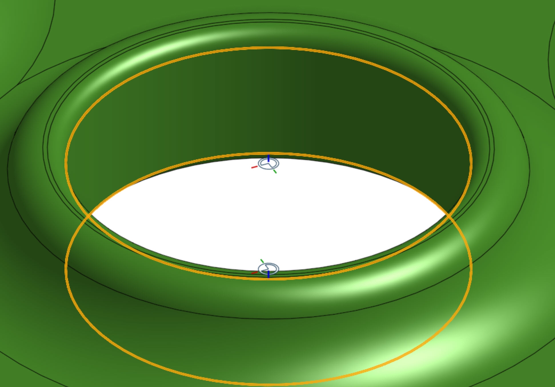
I have an object that requires an interference fit. The hole will be in plastic (3D printed) and the object is metal. Getting exact tolerances is painful since 3D printing is so variable so I am wanting to add small nubs or bumps to the inside of the hole since the plastic is malleable enough that these bumps will simply compress or shear away as needed to make the fit. Here is the hole in question (not a hole feature, just an extruded cylinder remove.

I would like to create a ring of nubs on the inner surface half way between the two selected curves. I was going to start by making a plane there however I can't actually work out a way to do that without creating extra geometry to derive the plane from. Is there no way to make planes from planar curves surrounding voids like this?
If I could make a plane I could presumably sketch a circle derived from the path selected, then make another plane on the end of that (although it seems point of curve doesn't work with closed curves). Then I could draw the profile, revolve it and then pattern the resulting part. This seems very complex and as can be seen there are a few roadblocks along the way I can't seem to solve.
They could also be ribs rather than bumps I guess, however I still have difficulty working out a way to create these. Note that I would obviously want it to be able to refit when I change the size of the hole. Am I missing a straight forward way to do this? In general the issue of creating planes on curves surrounding voids is something I have come across quite a bit actually.
0
Best Answer
-
 Paul_Arden
Member, Onshape Employees, Developers Posts: 226
  Actually that works pretty well, with the right constraints it is still parametric to the original hole size and isn't too hard to work with.
Thanks for the example document, I basically followed that exactly to get to this result. While extra sketches were needed I didn't have to make any redundant surfaces or parts so I'm happy enough with that, especially since I can easily modify the hole size now.0
Answers
https://cad.onshape.com/documents/8331d15630b35a24c141111b/w/0cbd83b60224be56f674efc3/e/f4cc466621b6b86b2fb058d5
https://cad.onshape.com/documents/1e7d31e433da1cc28ea16fc4/w/711f9cad463412cb59fd99db/e/98e3e113c1088f0ce780d32c
The real model has a lot of features after the hole so it's not really practical to roll back that. I should just write a FeatureScript for it if I am going to do this a bit but it seemed like something that should be relatively simple so I thought I might be missing something.
https://cad.onshape.com/documents/93d6bfbcf526bab6f89e0fad/w/8a6f11bdc20807834cda5a9e/e/cfaf75f2c2cb7f04e809fb24
Then again, I just re-read part of your OP. You mentioned you didn't want to create additional geometry, and that's what I did.
Thanks for the example document, I basically followed that exactly to get to this result. While extra sketches were needed I didn't have to make any redundant surfaces or parts so I'm happy enough with that, especially since I can easily modify the hole size now.