Welcome to the Onshape forum! Ask questions and join in the discussions about everything Onshape.
First time visiting? Here are some places to start:- Looking for a certain topic? Check out the categories filter or use Search (upper right).
- Need support? Ask a question to our Community Support category.
- Please submit support tickets for bugs but you can request improvements in the Product Feedback category.
- Be respectful, on topic and if you see a problem, Flag it.
If you would like to contact our Community Manager personally, feel free to send a private message or an email.
Threading a shaft
 RotarySMP
Member Posts: 8 PRO
RotarySMP
Member Posts: 8 PRO
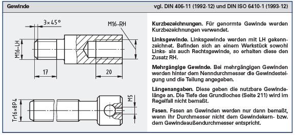
I see there has been some discussion about cosmetic threading, but I am only interested in a normal drawing representation of a shaft thread on a normal production drawing. I have a university assignment to prooduce a drawing of a spindle shaft, and can't see a way to create the thread on the shaft unless I draw each line into the drawing.
Is it not possible to assign a thread to a shaft in the model, and have this automatically draw the root diameter lines per ISO 6410?
https://ww3.cad.de/foren/ubb/uploads/AndreySCA/Gewinde.jpg
Is it not possible to assign a thread to a shaft in the model, and have this automatically draw the root diameter lines per ISO 6410?
https://ww3.cad.de/foren/ubb/uploads/AndreySCA/Gewinde.jpg
1
Best Answer
-
 Jake_Rosenfeld
Moderator, Onshape Employees, Developers Posts: 1,646
Jake_Rosenfeld
Moderator, Onshape Employees, Developers Posts: 1,646  @Mark_Wrathall I actually think I misread your post. You're looking for thread indications on the shaft, not the hole. Correct?
If this is the case, we don't currently have a way to do this, but you could use the thread creator to create actual threads on your shaft:
https://cad.onshape.com/documents/6b640a407d78066bd5e41c7a/w/4693805578a72f40ebfb4ea3/e/f8aea9e5c33e02eab0854a4f
Please raise an improvement request from the "Improvement request" section of this forum so that we can prioritize work of thread indicators on shafts.Jake Rosenfeld - Modeling Team5
Answers
Are you using the "Hole" feature to create your holes? Does this not provide what you need?
https://cad.onshape.com/documents/45a627679c685e7736438b6f/w/a8b3eed233d3b0ff316441ca/e/0c4508ad82e0e9912e20df13
https://cad.onshape.com/help/Content/hole.htm
If this is the case, we don't currently have a way to do this, but you could use the thread creator to create actual threads on your shaft:
https://cad.onshape.com/documents/6b640a407d78066bd5e41c7a/w/4693805578a72f40ebfb4ea3/e/f8aea9e5c33e02eab0854a4f
Please raise an improvement request from the "Improvement request" section of this forum so that we can prioritize work of thread indicators on shafts.
pictorially spaced about .03" (on paper) away parallel to the major diameter.
ALSO, while a centerline IS provided as a tool in the drafting system, a phantom line IS NOT. The phantom line is an essential tool for providing a sense of adjacent geometry without confusing it with the principal part the design.
Preferably just be able to click a shaft in the part studio and assign it a thread (not rendered in 3D) that would produce the correct 2D representation in a drawing
I'd like a threaded rod in a drawing without the cosmetic thread representation.
I don't have any update for you, but sending in a support ticket requesting the behavior will help us to prioritize the work.
To be fair its a 190 vote feature request hanging on from 2017...
https://forum.onshape.com/discussion/6857/external-cosmetic-thread#latest
In 10 yeatrs of engineering, I've seen it countless times.
I have a ready supply of people to vote for it if that will make a difference. I'm fed up with fudging drawings by adding sketches.
There are FeatureScripts to create actual thread geometry for those of us who like to see that.
Simon Gatrall | Product Development, Engineering, Design, Onshape | Ex- IDEO, PCH, Unagi, Carbon | LinkedIn
While the thread undercut is a good start, there are norms for those as well, as if you are doing this to prevent the stress concentration, you will probably use one of the DIN 509 options.
Mark