Welcome to the Onshape forum! Ask questions and join in the discussions about everything Onshape.
First time visiting? Here are some places to start:- Looking for a certain topic? Check out the categories filter or use Search (upper right).
- Need support? Ask a question to our Community Support category.
- Please submit support tickets for bugs but you can request improvements in the Product Feedback category.
- Be respectful, on topic and if you see a problem, Flag it.
If you would like to contact our Community Manager personally, feel free to send a private message or an email.
Fresnel Lens 3D model (rotationally symmetric spherical surfaces with a maximum sag from plane)
 RWS
Member Posts: 2 EDU
Hello, I am a very new user to OnShape and CAD in general, so bear with me as I try to explain what I am attempting to do.
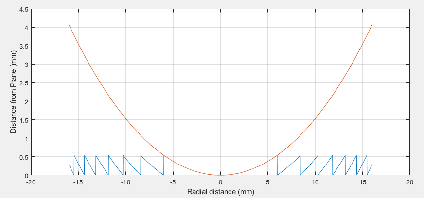
Firstly, a Fresnel lens is essentially a convex or concave lens with a defined thickness for each surface which when reached, the function defining the surface is set back to zero (essentially the modulo function).
The above image is an example of what I mean, where the curvature of the lens (red line) is kept, but it has much a much lower thickness (blue line).
The blue line above is what I would like to somehow model/import in this software, rotate around the central point (0,0) in order to make a Fresnel surface, which I would imagine is possible considering it is rotationally symmetric, then fill in the surface to make it a solid object connected to a circular plane.
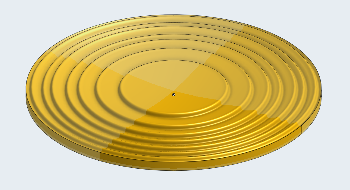
This is a model I have done by just exporting it from the design software as .stp file and importing to here, but if you just compare the surface of this model to the above graph, you'd notice that the steps don't exactly line up and that the original design software can't accurately model what we need.

So what I have been trying to do is using the function defined above in the first figure to write different points for vertices to be used in SkFitSpline and then somehow rotate that into a 3d surface, but I can't even get the SkFitSpline to properly work. I'm wondering if there is a way to just write a circular formula with a modulo function (like I did in Matlab) directly in OnShape to create the profile of the surface and rotate that or if there is some better way to do what I've been describing.
Essentially I just want to recreate the second image (there is a mirrored surface on the other side of the model that is same as the top surface but cannot be seen) but with the each successive ring being less wide (for lack of better words) and match the figure above.
If anyone could help that would be greatly appreciated. I can provide more information as needed.
Firstly, a Fresnel lens is essentially a convex or concave lens with a defined thickness for each surface which when reached, the function defining the surface is set back to zero (essentially the modulo function).

The above image is an example of what I mean, where the curvature of the lens (red line) is kept, but it has much a much lower thickness (blue line).
The blue line above is what I would like to somehow model/import in this software, rotate around the central point (0,0) in order to make a Fresnel surface, which I would imagine is possible considering it is rotationally symmetric, then fill in the surface to make it a solid object connected to a circular plane.
This is a model I have done by just exporting it from the design software as .stp file and importing to here, but if you just compare the surface of this model to the above graph, you'd notice that the steps don't exactly line up and that the original design software can't accurately model what we need.

So what I have been trying to do is using the function defined above in the first figure to write different points for vertices to be used in SkFitSpline and then somehow rotate that into a 3d surface, but I can't even get the SkFitSpline to properly work. I'm wondering if there is a way to just write a circular formula with a modulo function (like I did in Matlab) directly in OnShape to create the profile of the surface and rotate that or if there is some better way to do what I've been describing.
Essentially I just want to recreate the second image (there is a mirrored surface on the other side of the model that is same as the top surface but cannot be seen) but with the each successive ring being less wide (for lack of better words) and match the figure above.
If anyone could help that would be greatly appreciated. I can provide more information as needed.
0
Comments
https://cad.onshape.com/documents/b052d208db31db1d906b4cff/w/f6e937230f44746f12876c62/e/c0367b0dc4dad834d1b26715
The pre-modulo equation goes into the Z component of the Parametric Curve feature (second feature from the top)
The number of slices is controlled by the #Count variable.
Hope this helps.
https://cad.onshape.com/documents/4cf38e9f5e5cbf90c8c3660a/w/4e81ef21520f09df991e0792/e/5ed997431f5d9336aaccf8a2