Welcome to the Onshape forum! Ask questions and join in the discussions about everything Onshape.
First time visiting? Here are some places to start:- Looking for a certain topic? Check out the categories filter or use Search (upper right).
- Need support? Ask a question to our Community Support category.
- Please submit support tickets for bugs but you can request improvements in the Product Feedback category.
- Be respectful, on topic and if you see a problem, Flag it.
If you would like to contact our Community Manager personally, feel free to send a private message or an email.
How to Planar mate two parts with a precise offset?
 ts_sklett
Member Posts: 9 ✭
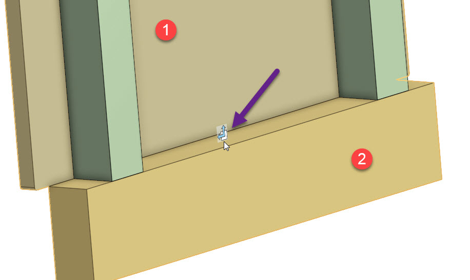
I am in the early stages of drawing one of our machines (reverse engineering). I have added some parts to an assembly and would like to mate them together (part 1 and part 2). I think a planar mate connector is appropriate, but I don't understand how the offsets are controlled. I created my mate and the edges snapped to the same location (expected). I then noticed when I hovered over the area a new icon (new to me) appeared, here it is:

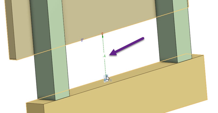
Using the triad I moved part 1 upwards. I then noticed there was a new "dimension" displayed and while it's awesome because it seems to be just what I want, I have no idea *what* it is and how to manage it. Here is the magic dimension I'm referring to:

I pulled up the properties on the mate connector and I don't see a maximum or minimum has been set, so I really don't get what that -4 dimension is.
Can anyone shed some light on this for me?

Using the triad I moved part 1 upwards. I then noticed there was a new "dimension" displayed and while it's awesome because it seems to be just what I want, I have no idea *what* it is and how to manage it. Here is the magic dimension I'm referring to:

I pulled up the properties on the mate connector and I don't see a maximum or minimum has been set, so I really don't get what that -4 dimension is.
Can anyone shed some light on this for me?
Tagged:
0
Answers
What you're saying matches with what I experienced: I used a planar mate and chose points on the opposing planes I wanted to mate. In this one case I only needed to move the part up in the Y direction which means that if I managed to make Z the desired axis of the offset I *could* use the offset tool, however if I wanted to offset in two directions this would not work.
I'm still wondering what function or tool is providing the offset and control illustrated in this screenshot:
Also, you mentioned clicking on an edge. Creating a mate connector on a linear edge will align its Z axis with that edge. In your case, I would click on the mating surfaces, not edges. That will give you mate connector Z axes that line up with each other.
By the way, when I'm talking about X, Y, and Z I'm not referring to the global XYZ axes. I'm talking about the mate connector axes.
Onshape mates work differently than most other CAD systems. Using our mates correctly, you can use many times less mates than in other systems. Can you describe the motion (or lack thereof) that you are trying to accomplish here? I would only use a planar mate here if you want those plates to be able to slide along each other in both directions, otherwise if you want them locked together or only sliding along one axis, there are more specific mates you can use.
https://cad.onshape.com/help/Content/mate-fastened.htm
https://cad.onshape.com/help/Content/mate-slider.htm
https://www.onshape.com/videos/assembly-mates
PS: A good way of describing the 'offset' option here is that it keeps the motion of the two parts planar to each other, but offsets them away from each other (decides a distance that they sit from each other). To limit the motion in the planar directions, you would use the 'limits' checkbox, but if you're trying to entirely suppress one or two degrees of freedom using the limits here, you should use the slider or fastened mate, respectively.