Welcome to the Onshape forum! Ask questions and join in the discussions about everything Onshape.
First time visiting? Here are some places to start:- Looking for a certain topic? Check out the categories filter or use Search (upper right).
- Need support? Ask a question to our Community Support category.
- Please submit support tickets for bugs but you can request improvements in the Product Feedback category.
- Be respectful, on topic and if you see a problem, Flag it.
If you would like to contact our Community Manager personally, feel free to send a private message or an email.
Why is my sheet metal flat view reversed from my isometric view?
 verne_severson
Member Posts: 3 PRO
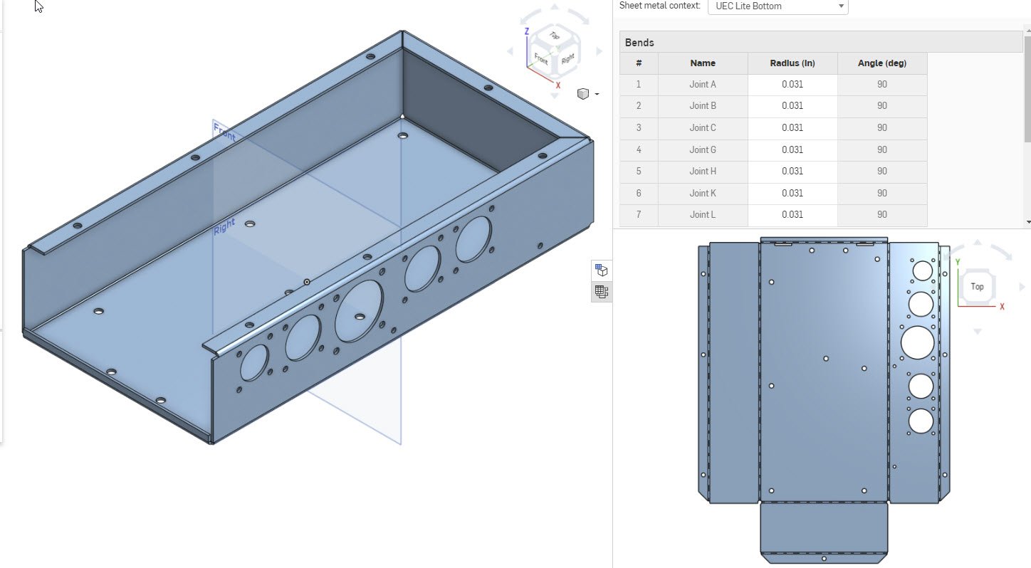
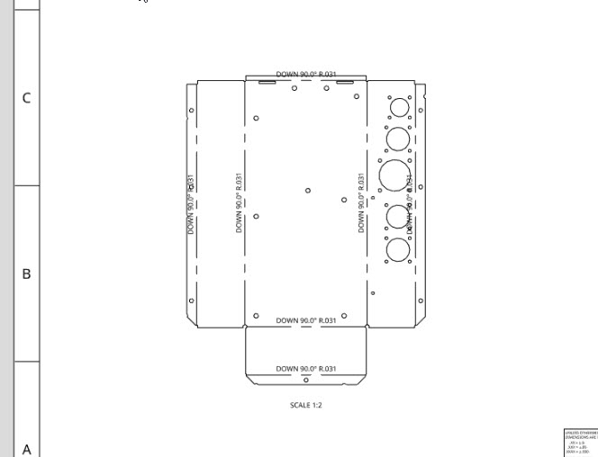
My sheet metal flat view is reversed from my isometric view. The Axis Icon in the flat view is reversed from the Axis Icon in the drawing area of the Parts Studio. And when I bring it in to a drawing it is reversed. It looks like it would still bend properly if we are willing to put up with all bends shown as "Down". My other projects show the flat view properly. If I flip the flat view over, I lose the bend lines and bend notes.
Help needed. Did I make a wrong setting somewhere??


Help needed. Did I make a wrong setting somewhere??


Tagged:
0
Best Answers
-
 lana
Onshape Employees Posts: 757
  @verne_severson
Could you please submit this via Feedback tool (In ? menu) to support and share your document.6 -
 Jason_S
Moderator, Onshape Employees, Developers Posts: 224
  Right now there is no way to define the 'up' direction in sheet metal models. We pick an 'up' for you on body creation and all of the bend directions are relative to that. Like you pointed out, your model won't be built incorrectly, it is just isn't the direction you wanted.
We also only show the bend centerlines and bend notes on one side.
We know this is an issue and are looking to address it in the future.Support & QA6
Answers
Could you please submit this via Feedback tool (In ? menu) to support and share your document.
We also only show the bend centerlines and bend notes on one side.
We know this is an issue and are looking to address it in the future.
I found that I can affect making the flat view match the isometric view. The problem happens when using Extrusion to start a sheet metal project.
Solution: When viewing the sketch to make the Sheet Metal Model, it makes a difference on the order I select the edges to extrude:
Does Not Work: Select left, bottom, and right.
Does work: Select right, bottom, left.
So I started the whole project over again, this time selecting the edging in the other order. Now the flat view matches the isometric view.