Welcome to the Onshape forum! Ask questions and join in the discussions about everything Onshape.
First time visiting? Here are some places to start:- Looking for a certain topic? Check out the categories filter or use Search (upper right).
- Need support? Ask a question to our Community Support category.
- Please submit support tickets for bugs but you can request improvements in the Product Feedback category.
- Be respectful, on topic and if you see a problem, Flag it.
If you would like to contact our Community Manager personally, feel free to send a private message or an email.
How to model a lens shade for 3d filament printing...
 max_rockbin
Member Posts: 7 ✭
max_rockbin
Member Posts: 7 ✭
I'm new to CAD and have been trying to figure out how to model a microscope lenshade with the following approximate specs:
Bottom profile is a circle approx 19mm diameter
Above it about 20mm, the opening profile is a rectangle approx 1.5x2.5mm
(this is for a microscope lens, so the subject end is narrower than the back end)
So it's sort of a cone with a cut off squared pointy end.
That's a straightforward loft with the surface thickened (to 2mm). The tricky part is that the inside has to have grooves about 1mm deep concentric to the axis. The grooves would be separated by 0.3mm and span about 2mm.
They would be rectangular grooves perpendicular to the central axis (lofting path of the hood).
Ideally, the grooves would be trapezoidal, so the deepest part would actually be at a 45 degree angle at the bottom, giving support to the upper wall of the groove as it is being 3d printed (about 1/2mm of the wall depth would still be cantilevered).
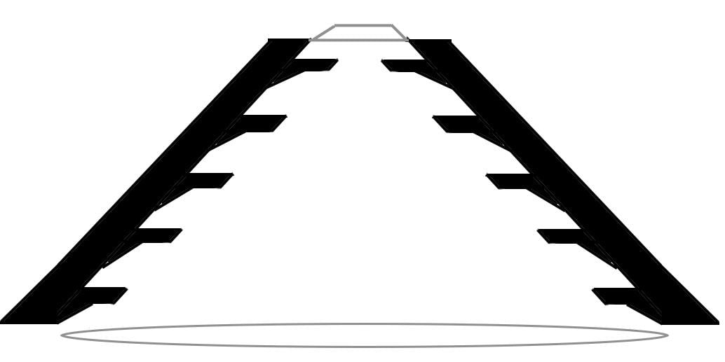
Here's a rough drawing. In the real hood there would be many more grooves and the angles and proportions are a little different. The idea is that the front business end of the hood ideally will match the shape of the field of view (DSLR sensor proportions) and the part that mates with the lens naturally has to have the round shape of the front of the lens. The idea is to limit light rays from outside of the field of view from striking the front of the lens. The slots (baffles) reduce reflections that would be visible to the lens from stray light striking the side of the hood.
If it is not practical to do this, I can just do a revolve of the profile around the axis and have a more typical conical lens hood. But a nice thing about 3d printing is no additional cost for printing eccentric shapes.
Bottom profile is a circle approx 19mm diameter
Above it about 20mm, the opening profile is a rectangle approx 1.5x2.5mm
(this is for a microscope lens, so the subject end is narrower than the back end)
So it's sort of a cone with a cut off squared pointy end.
That's a straightforward loft with the surface thickened (to 2mm). The tricky part is that the inside has to have grooves about 1mm deep concentric to the axis. The grooves would be separated by 0.3mm and span about 2mm.
They would be rectangular grooves perpendicular to the central axis (lofting path of the hood).
Ideally, the grooves would be trapezoidal, so the deepest part would actually be at a 45 degree angle at the bottom, giving support to the upper wall of the groove as it is being 3d printed (about 1/2mm of the wall depth would still be cantilevered).
Here's a rough drawing. In the real hood there would be many more grooves and the angles and proportions are a little different. The idea is that the front business end of the hood ideally will match the shape of the field of view (DSLR sensor proportions) and the part that mates with the lens naturally has to have the round shape of the front of the lens. The idea is to limit light rays from outside of the field of view from striking the front of the lens. The slots (baffles) reduce reflections that would be visible to the lens from stray light striking the side of the hood.
If it is not practical to do this, I can just do a revolve of the profile around the axis and have a more typical conical lens hood. But a nice thing about 3d printing is no additional cost for printing eccentric shapes.
0
Best Answers
-
matthew_menard
Member Posts: 96 ✭✭✭
Sorry, I should have named the features to give a better idea of what I did.
I started with a loft that was arbitrarily offset 3mm from the dimensions in your sketch to make the outer body. Then made a remove loft that was to the diameter of the lens and aperture in the sketch. After that, I offset a plane 2mm off the base and used that to cut the body along that plane. Next was a sketch on that plane. In that sketch, I selected the edges of the cut bodies and converted them into the sketch. The converted geometry was then offset by 1mm. I then extrude added it to .3mm and merged the whole thing back together. That process was repeated again with a new plane offset by 2mm.
Hope that makes it a little clearer, it's late though so I make no warranty on how clear my description is.
1 -
 russ_taber
Member Posts: 11 ✭✭
This should be dimensionally accurate. Basically I modeled the negative space then subtracted it from a larger solid.
russ_taber
Member Posts: 11 ✭✭
This should be dimensionally accurate. Basically I modeled the negative space then subtracted it from a larger solid.
Doing this from my iPad Mini so hopefully this link is accurate or search for 'lens hood'. Delete the last element to remove the cut-away. Fun challenge.
https://cad.onshape.com/document-redirect.html?d=/documents/2ac5ee76fc3b4716966f9212/w/dcbfab62d24b474786f9c4b5
4 -
russ_taber
Member Posts: 11 ✭✭
max_rockbin, you're more that welcome.
I cleaned up the document and named the parts for better clarity.
I ran into a couple issues that I fixed.
Wanting to make a larger shell, I first tried making sketches of the top and bottom and offset them by 1.2mm (or whatever your thickness. OnShape wouldn't Loft them--even turning the initial shapes to reference lines. Gave up at lofting and tried to Thicken it. Nope. Worked 'thinning' going in but not out. So tried scaling and chopping the top--which I first submitted to you.
Going back today, I tried lofting again, but use a reference point and then set dimensions in the end sketches to make my own offset.
You should be able to rollback to see how I built it. If you change the number of crosscuts, you'll probably have to go back and fix it. But editing the dimensions in the sketches should not break the model.
Also, the opening had a bit of a rotation happening from the lofting. So I segmented (split) the circle to add 4 points. This allows to set the loft to match vertices and keep it from twisting.
Again, I split the part so you could see the cross section. Setting it to transparent didn't show as well. Rollback one feature and your part will be whole.
I did try printing a sample on my 3D printer at 0.1mm layer height with no supports. The lower layers were okay, but the top layers got a bit wonky. Might be printing a bit too fast, and is pushing my $450 printer a bit.
OnShape is my first exposure to parametric modeling and I love it. So glad have access to it as it continues to grow.5
Answers
Thanks
Then create a series of planes that intersect the "cone" perpendicular to its axis where the grooves are desired and derive circles where the planes intersect the cone (on the inside). Then use those circles as sweep paths for a shape that would cut the grooves (sweep with subtract selected). But I haven't managed to do this successfully. I don't know how to isolate the circles (actually circle rectangle hybrids) where the plane intersect the lofted cone so they can be used as sweep paths and haven't managed to get the sweeped shape positioned correctly to cut the groove.
My first thought would be to mass-produce a stack of sweep paths in virtual space, a bit like a stack of flight paths over an airport.
You can do this by lofting a single surface, between a circle and a round cornered rectangle (see note 1)
Then create a stack of planes, one for each groove
Now you can produce a generic sketch of a round-cornered rectangle with minimal constraints, and paste it into each sketch. (see note 2) then constrain the entities to the surface mentioned above.
Note 1: the circle will need to be split into as many arcs as the total number of segments in the other profile, presumably 8
Note 2: this palaver is necessary (or some other workaround - I expect another user will have a better one) because Onshape does not yet provide "intersection curve" facility, unless it snuck in while I was asleep.
See link
https://cad.onshape.com/documents/e8eb4bc908ba4bf1a490bc07/w/217f4cf449564267b54d0f99/e/45afa940ec3742d6a9137a06
When you say "take a stab and adjust," are you suggesting making a profile and revolving it to create a cone and adjusting that somehow to square of the top? If so, how does one do that in OnShape?
I've been taking a few stabs at this hood with no luck on my own so far. I can fall back to a simpler form, but OnShape seems so powerful, I just figured there must be a way...
I tried to do one more level, but it doesn't seem to like the geometry that was getting made when I offset the profile in.
https://cad.onshape.com/documents/4d3a3befc86f475c86e135ad/w/ea2bd8a23ebc4bdcbf2079cf/e/3d0e620d29614a22a6cf132d
Hope this helps.
In an ideal world all of those circular disk cut outs on the interior would follow the same progression from circular to rectangular as the main shell. Maybe I could do that by replicating a smaller version of the main shape and subtracting it from the interior.
But how did you make all those interior grooves? I can see you used disks (which I think you generated with a revolve?)
Thanks!
I think you nailed it! That's great. Can you explain something of the steps involved?
I'm not following the steps very well just from the document.
I started with a loft that was arbitrarily offset 3mm from the dimensions in your sketch to make the outer body. Then made a remove loft that was to the diameter of the lens and aperture in the sketch. After that, I offset a plane 2mm off the base and used that to cut the body along that plane. Next was a sketch on that plane. In that sketch, I selected the edges of the cut bodies and converted them into the sketch. The converted geometry was then offset by 1mm. I then extrude added it to .3mm and merged the whole thing back together. That process was repeated again with a new plane offset by 2mm.
Hope that makes it a little clearer, it's late though so I make no warranty on how clear my description is.
My suggestion was in response to your proposal to produce "sweep paths for a shape that would cut the grooves (sweep with subtract selected)."
It was not a method for creating a solid hood, simply for adding grooves to an existing model.
It was aimed at mass-producing a stack of paths with the desired characteristics.
The "adjust" I had in mind was a simple variation of the dimensions of the two end profiles, using the parametric capabilities to maintain their essential character, to bring the grooves to the correct depths.
Doing this from my iPad Mini so hopefully this link is accurate or search for 'lens hood'. Delete the last element to remove the cut-away. Fun challenge.
https://cad.onshape.com/document-redirect.html?d=/documents/2ac5ee76fc3b4716966f9212/w/dcbfab62d24b474786f9c4b5
I just copied it to my own workspace and went through every step and edited each step so It would display the part at that point in the history and what settings were used. Everything is perfectly clear. A very clever solution and it shows what you can do with a good tool in good hands. Thanks Again!
I cleaned up the document and named the parts for better clarity.
I ran into a couple issues that I fixed.
Wanting to make a larger shell, I first tried making sketches of the top and bottom and offset them by 1.2mm (or whatever your thickness. OnShape wouldn't Loft them--even turning the initial shapes to reference lines. Gave up at lofting and tried to Thicken it. Nope. Worked 'thinning' going in but not out. So tried scaling and chopping the top--which I first submitted to you.
Going back today, I tried lofting again, but use a reference point and then set dimensions in the end sketches to make my own offset.
You should be able to rollback to see how I built it. If you change the number of crosscuts, you'll probably have to go back and fix it. But editing the dimensions in the sketches should not break the model.
Also, the opening had a bit of a rotation happening from the lofting. So I segmented (split) the circle to add 4 points. This allows to set the loft to match vertices and keep it from twisting.
Again, I split the part so you could see the cross section. Setting it to transparent didn't show as well. Rollback one feature and your part will be whole.
I did try printing a sample on my 3D printer at 0.1mm layer height with no supports. The lower layers were okay, but the top layers got a bit wonky. Might be printing a bit too fast, and is pushing my $450 printer a bit.
OnShape is my first exposure to parametric modeling and I love it. So glad have access to it as it continues to grow.
Muchos kudos to you, @russ_taber !