Welcome to the Onshape forum! Ask questions and join in the discussions about everything Onshape.
First time visiting? Here are some places to start:- Looking for a certain topic? Check out the categories filter or use Search (upper right).
- Need support? Ask a question to our Community Support category.
- Please submit support tickets for bugs but you can request improvements in the Product Feedback category.
- Be respectful, on topic and if you see a problem, Flag it.
If you would like to contact our Community Manager personally, feel free to send a private message or an email.
Advice wanted please - spur gears not meshing.
 jayne_parker
Member Posts: 7 ✭
jayne_parker
Member Posts: 7 ✭
Hi All,
A spot of advice needed from anyone expert with spur gears…
I added a custom feature for creating spur gears and 12 and 48 teeth for the RC car I'm designing. They look ok in Onshape but don't mesh well when printed. The larger gear is incorporated into the rear wheel & so the overall dimensions are pretty fixed. If anyone is interested the project as it stands can be found on Makerworld https://makerworld.com/en/models/1237561-rc-mini-stock-car-chassis-1-12#profileId-1257524Error
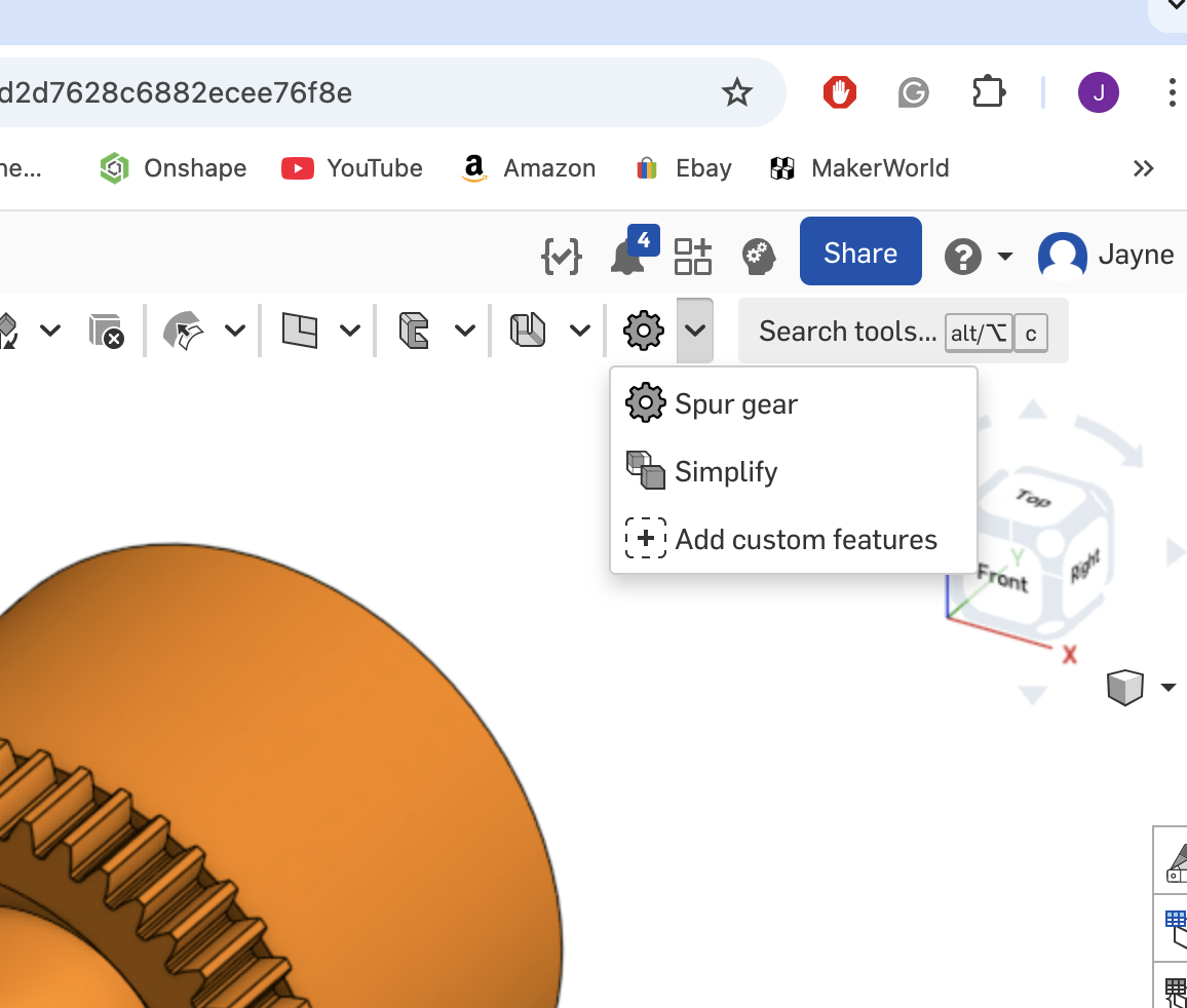
I am a bit of a noob with gears and wonder if someone could suggest what I should use as settings in the dialogue box. The document can be found here https://cad.onshape.com/documents/8de2d0aa13db7fb4d753c38b/w/75f97d67d83752dfef0c838c/e/3c70d94b2afd787591f833be?renderMode=0&uiState=67f0f42cdfba955626caa50f
The aim is to 3d print and perhaps machined in metal if the plastic proves not to be durable enough.
Thanks, Jayne. 😀
Comments
@jayne_parker
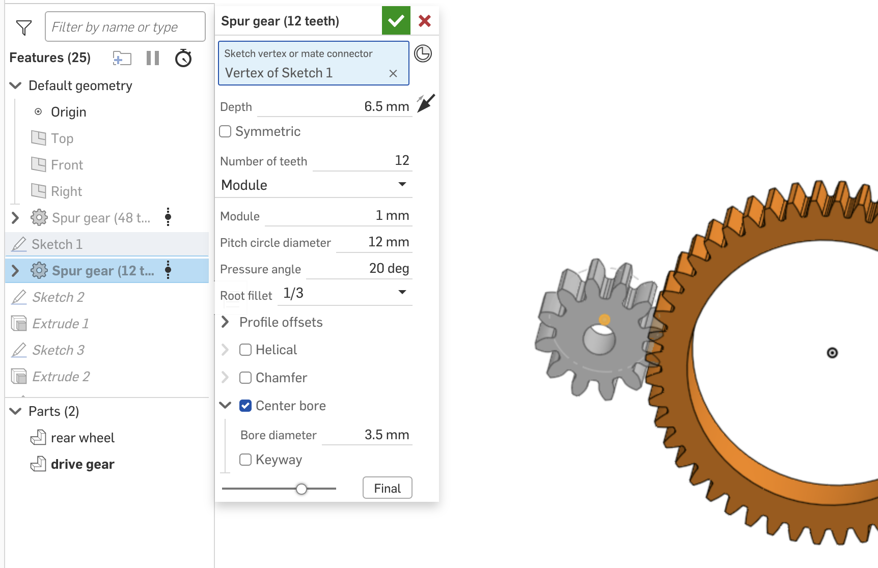
First, try setting your module
idealidentical in both gear features, then play with other dimensions to get them to fit the space.@jayne_parker …If you want your gears to "mesh" perfectly in the sketch you need three things:
1) as Wayne mentioned above, both gears need to have the exact same Module count
2) The Pitch Circle Diameters of both gears must meet at a tangency to each other (if using the Spur Gear FS unfortunately this cannot be accomplished using simple mates).
I accomplish this by first adding a construction line that is longer than needed, then measure the minimum distance between the pitch circles, then finally subtracting that measurement from the length of the original construction line.
3) One of the Gears must be rotated to an angle that represents the angular offset that relates to the number of teeth in that gear.
In this case the 12 tooth gear has a angular offset of 15 degrees [360 degrees / 12 teeth / 2 (half a tooth)]. To make the rotation easier I modeled the 12 tooth gear on a Mate Connector of the construction line, and then rotate that Mate Connector the appropriate angle.
Final result….
An even simpler way is to sketch that construction line to the needed angle in the first place!!! 🤓. This eliminate the need to Rotate…