Welcome to the Onshape forum! Ask questions and join in the discussions about everything Onshape.
First time visiting? Here are some places to start:- Looking for a certain topic? Check out the categories filter or use Search (upper right).
- Need support? Ask a question to our Community Support category.
- Please submit support tickets for bugs but you can request improvements in the Product Feedback category.
- Be respectful, on topic and if you see a problem, Flag it.
If you would like to contact our Community Manager personally, feel free to send a private message or an email.
Loft between ends of two tubes in different planes.
 oliver_richards_grubb
Member Posts: 2 ✭
I'm very new to onshape and 3d modelling in general.
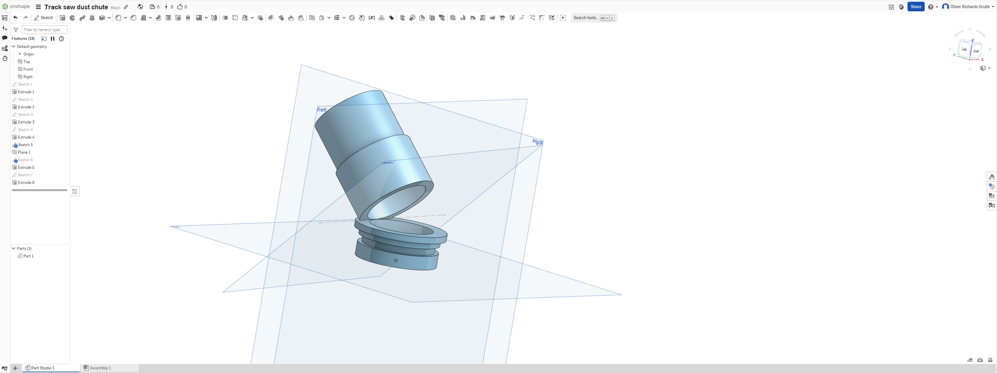
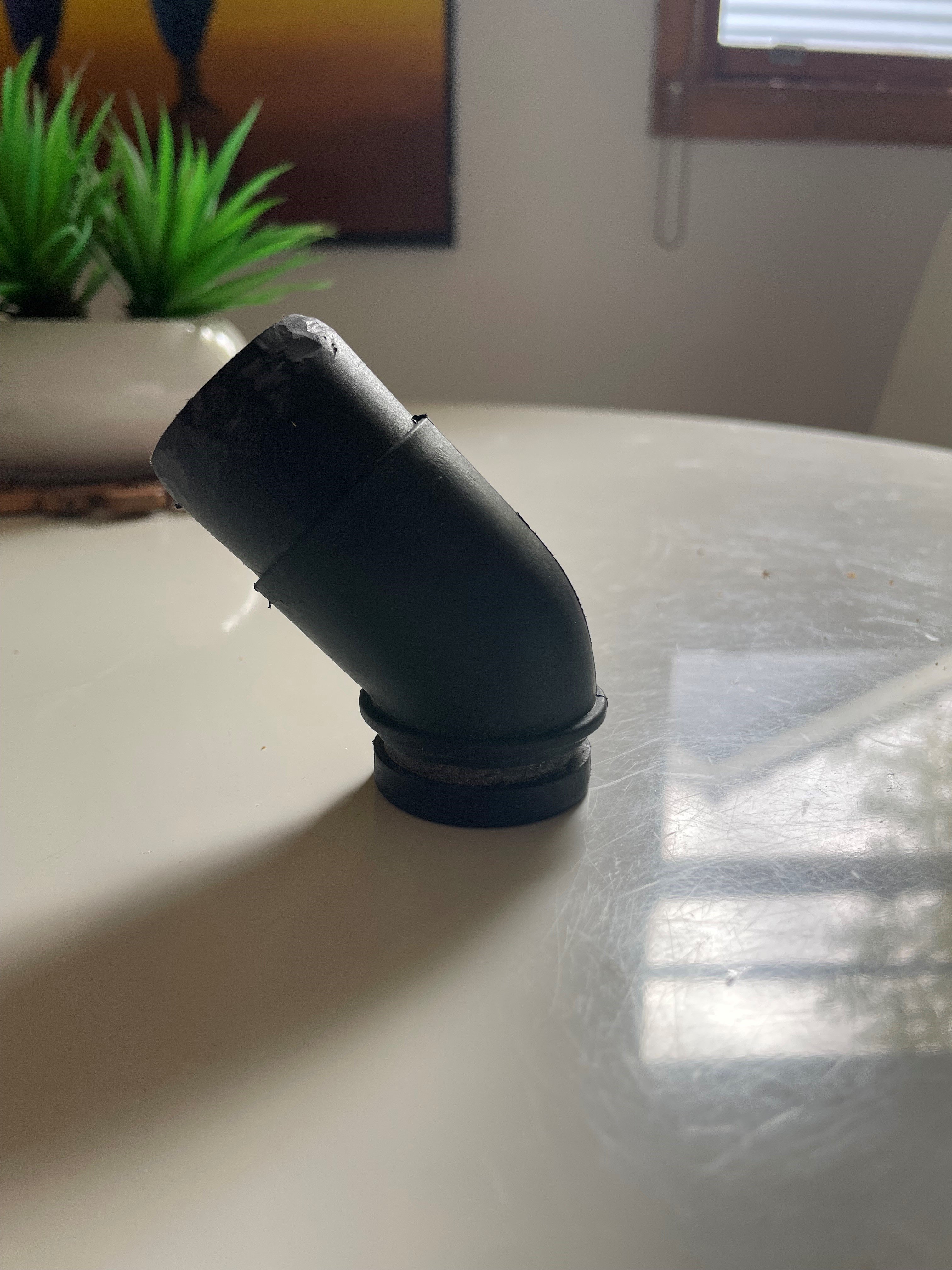
I'm trying to model a dust extractor fitting that has a 45-degree bend in it and cannot get the transition between the parts to work.
From what I can tell, I should be able to use the sweep function to connect the two surfaces with a 4mm wall, but I can't get it to generate at all.
This is the part that I'm trying to replicate, for reference:
https://cad.onshape.com/documents/5c9898979675bf55767b7ab3/w/e067d85a7fca5b345fd14403/e/ad8faffdf199cd23783e1b4f


Comments
Hey Oliver. Welcome to Onshape.
I took a look at and played around a bit with a copy of your document. I think what mostly contributed to the failure of the loft is back in Sketch 5 from which you created Plane 1. The construction line you drew is skewed at an (whaich I think is unintended) odd angle resulted in Plane 1 to be also. Adding a horizontal constraint to that line made that sketch fully constrained and corrected that problem. If you stick with Onshape and frequent the forums you will read about (or may experience yourself) problems with sketches that are not fully defined. Although not required in continuing to build a model, you're likely to regret it later if you do not get a sketch or sketches to go all black (fully defined).
Continuing: All the sketches and extrudes 1 thru 4 could (in a cleaner way) be replace with one sketch containing a profile of the lower part of the piece you are modeling and a revolve.
I think a more robust, cleaner way to approach this model is to start with a sketch representing the path of the model's center line and then a Thin sweep of 2mm along that path using a sketch of the model's I.D., leaving a base part to continue to build on. Here's my copy of your document. - Scotty
P.S. Being wary that the sweep might fail due to a too tight radius (which it did), I created a variable to use for the radius of the bend in the sketch of the tube's centerline. Using that variable in the Variable Table, I was able to 'tweek' that radius until it did not fail.
@oliver_richards_grubb …. the best approach would be to use a Sweep Feature for the primary shape..and then a series of Revolves and Extrudes to add the details…