Welcome to the Onshape forum! Ask questions and join in the discussions about everything Onshape.
First time visiting? Here are some places to start:- Looking for a certain topic? Check out the categories filter or use Search (upper right).
- Need support? Ask a question to our Community Support category.
- Please submit support tickets for bugs but you can request improvements in the Product Feedback category.
- Be respectful, on topic and if you see a problem, Flag it.
If you would like to contact our Community Manager personally, feel free to send a private message or an email.
Tabs on Sheet Metal?

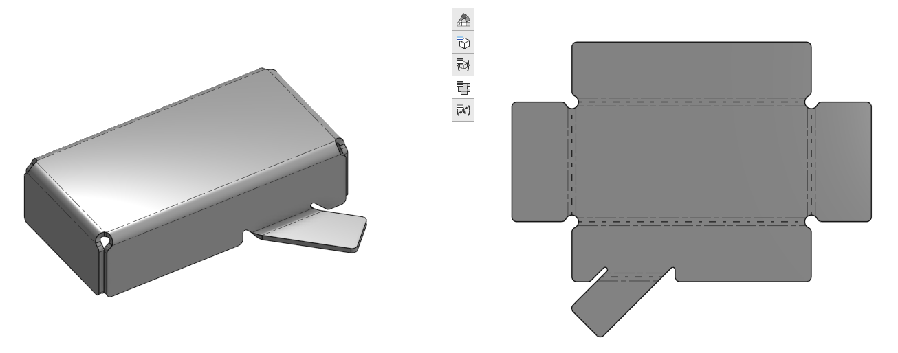
One of my co-workers asked me how to do something like this in sheet metal, and I just assumed that the sheet metal Tab feature would do this. It turns out it does not. It only adds material to the flat outline of a part of a sheet metal part. Partial flanges are great if you want the sides of that to be normal to the bend. In order to do this angled tab, I had to sketch the tab and add a bend. To avoid the worst bend relief I've ever seen, I had to create these by sketching and extrude/remove myself.
The results of this still don't get the tab in the exact right place. I can use move face, but that leaves weird artifacts.
There has to be a better way to do this. Do I need to create an improvement request, or am I missing something basic?
Simon Gatrall | Product Development, Engineering, Design, Onshape | Ex- IDEO, PCH, Unagi, Carbon | LinkedIn
Comments
In other CAD systems I belive this is called a sketched flange?
I think this also includes the need to be able to join 2 sheet metal parts together joined at a bend or something? Would be handy for sure!
Bricscad has this
Let me know if you do an improvement request I'll up vote it.
@S1mon
I've just run into that same issue last week. I don't frequently do sheet metal, these days, but I was expecting some things from the days when I did my CAD things in Spaceclaim. They had (and possibly still have) a sheet metal environment they developed together with the well known sheet metal machine manufacturer Trumpf, and got quite some input from them. With Spaceclaim being a direct modeler in most parts, the approach was different, though. Anyway, tabs like these, and all types of flanges that would only occupy part of an edge, were a breeze to make, pattern and modify. Things like the relative position of tabs on an edge or the width of a tab could be defined by driving dimensions. Bend reliefs were always following the modifications made to a tab. It not actually being a feature, some kind of feature-like algorithm took care of that. Anyway, it was highly usable and had a ton of dedicated tools. All these were accessible in a tab/sheet metal stuido in the Spaceclaim GUI.
When making these relatively simple tabs in OS, recently, I expected someting similar to happen, but I was surprised that even creating simple tabs of a specified width, that didn't go all along an edge was a difficult thing to do, and it required a lot of partially contardicting steps to finally get what I wanted. Finally I had to draw the reliefs first, just in order to get a manageable sketch- or dimension-driven flange/tab width. Me manually making the reliefs is not how a sheet metal toolset is meant to work, though. That was pretty disappointing.
OS sheet metal makes it hard to design possible stuff (left) while it lets me do impossible stuff (right) without hesitation:
So, whenever you feel like creating an improvement request, let me know and I'll create 20 more onshape accounts just to vote for it! ;0)
@martin_kopplow Could you please post a public doc link to the above model? The circle on the right looks like it would self-intersect in the flat, which we should flag reliably.
https://cad.onshape.com/documents/d627297851b19f1b78369d68/w/390014e0bdf3c1af983da7a2/e/8a6b37e0117576fedb8f9c40?renderMode=0&uiState=68c6c6ef30516545884c939c (Public Link.)
@ilya_baran Yes, that is clearly self-intersecting in more than one way. I'd also be happy if I knew why I had to trick OS into doing the things in the left circle, that is make the tab flush with the flange.
@martin_kopplow I am not a SM expert by any means but I don't think the sketch+tab+move face thing is necessary — I made a copy of the doc and two configs — one with your method and one with just one flange feature and they look exactly the same to me: https://cad.onshape.com/documents/490b0d490d451f9e51682d46/w/b772f092a1bfa74356c3f228/e/0e84aef38b15796930b0d06c
(I did not redo the downstream references in the one-flange config, but they should not be a problem)
The self-intersection is being reported (if you open Flange 5 or later) and shown in red on the flat but it's not failing the feature; do you feel like the blue bubble is not enough and the system should not let you create the geometry at all?
@ilya_baran
I am not a SM expert either, I sometimes do it if a project requires it, though. In this case, my intent was to create a partial flange (or a bent tab, should need be) of a specific width. The partial flange tool does not have a width option, and with nothing but the part available, the up to entity options were too much depending on entities subject to downstream edits. So I was led to make that sketch and create a tab of the desired width, then bend that. Now, when you recreated it, you used the partial flange feature right away, but you already had my sketch to pick the width from. This simple trick didn't come to my mind when I had my first go at it. I could have worked around the limited choice of options in the flange tool by first creating a sketch containing only the "up-to-entities" I could then pick to control the flange width and position. Lesson learned.
It appears the partial flange does not allow the two end positios to be measured from the same up-to-entity (one with an offset), right? In that case, I could have used a variabe for the tab/flange width.
Regarding the self intersection, there was no blue bubble I was aware of, and if it was there, it was pretty unobtrusive for a warning. I use a 34" screen in home office and so it might have been half a meter away from the action at the time. Thank god it wasn't in the offfice, for the screen there is 86".
I would expect the self intersecting volume (and exactly the volume) to be flagged in red. That would actively support the design process. I think it should only be flagged, not broken or prevented, because of downstream issues, and because editing might not yet be complete at the time, with later steps possibly eliminating the self intersection. It might be a good thing to display a clear warning when closing the feature with self-intersection still present, though.
@martin_kopplow
That's a very important thing you mentioned regarding failed sheet metal should be just flaged and not prevented from happening. I call this process a soft fail. This is where the 3D model still generates and allows you to do further downstream edits on the sheetmetal part where we then can fix the clashes. For example for cylinders and cones I find putting a rip/thin extrude cut in after more intuitive then trying to sketch a partial circle that you extrude/loft from. This means my tree has red sheetmetal parts all over it LOL. Would be good if a red sheetmetal feature turns green when you fix up clashes down stream. More sheet metal features the happier I am, pointing to SM loft.
@martin_kopplow I just looked and flange does have an "up-to-entity-with-offset" option available, so I reworked the document to not reference your sketch. That's not quite the same as a width option, but I think if you want to control design intent at that level, you are better off creating a construction sketch anyway.
I like the idea of the self-intersection highlighting in red in 3D, not just in the flat (because I guess you didn't have the flat view open when modeling) — please create an improvement request (with just one account per real person please! :) so we can track interest.
I opened a request, for people to vote:
Yes, there is an up-to-with-offset partial flange option, but that will always reference to elements of the model that will almost certainly change when editing the sheet metal part, such as the (two!) ends of the (full) flange edge. I couldn't reference both to one end with different offsets. They do apparetly work in opposite directions. I'll stick to the sketch option, then, I suppose.
I think there should also be a width option for the partial flange. That would feel only natural and should not be overly hard to do.
I would vote for a partial flange that is symmetric around a point on an edge. That point could be a vertex, offset from a vertex, mate connector, or percentage along the edge.
Simon Gatrall | Product Development, Engineering, Design, Onshape | Ex- IDEO, PCH, Unagi, Carbon | LinkedIn
@martin_kopplow
You can use "up to entity with offset" and two variables one for the width of the tab and one for the "offset".
Yes, sounds reasonable. Maybe add that to the request?
I made a separate improvement request:
Simon Gatrall | Product Development, Engineering, Design, Onshape | Ex- IDEO, PCH, Unagi, Carbon | LinkedIn
I had also made a separate improvement request recently for partial flanges.
https://forum.onshape.com/discussion/26574/partial-flange-extent-instead-of-offset-and-select-which-corner-it-starts-from
@jonathanb_sydney
I had missed that when I was searching for prior IRs.
Also the key comment from @eric_pesty mentioning @MBartlett21 's shaped flange feature:
https://carbon.onshape.com/documents/602655eff016f183fc184978/w/c20bffc426bdb249281c9a38/e/4ba4dfed9e2179c8f9c826ee
I've already added this to my toolbar and will be trying it out…
Simon Gatrall | Product Development, Engineering, Design, Onshape | Ex- IDEO, PCH, Unagi, Carbon | LinkedIn
So I tried out "Shaped flange" and it does a pretty nice job, if I'm willing to make the actual bend area normal to the edge with some margin. If I try to do something like my more hand built approach , the bend relief is terrible (Onshape issue).
The hand-built approach is in the upper left on the flat pattern.
The simple Shaped flange is on the lower left, the slightly more complex Shaped flange is on the lower right.
I added corner breaks to get the rounds, and if I didn't make the bend relief huge (scaled rectangle 2 wide), the flat pattern crashes for the lower left flange.
Simon Gatrall | Product Development, Engineering, Design, Onshape | Ex- IDEO, PCH, Unagi, Carbon | LinkedIn
The Shaped Flange FS will remove material where it shouldn't:
That was also one issue I first had when I tried the built-in partial flange. I think it should not interfere with this edge at all. I see why this might be a thing, but I can make certainly flanges like that with narrow tools, so why this limitation? (Especially when it only applies up to the next flange, not the whole edge, see image below).
To correct for that, one might think it was a good idea to use the move face tool, but that'll only let you move the egde back to it's former position when the offset option is elected and at least a very small offset relative to the original edge is used. What is the logic behind this?
@martin_kopplow
Yes. I was having that issue sometimes. It's nice that Move face can fix things, but one shouldn't have to do that so much.
Simon Gatrall | Product Development, Engineering, Design, Onshape | Ex- IDEO, PCH, Unagi, Carbon | LinkedIn
Yeah the "shaped flange" is useful but could use a "refresh" as it's got some limitations/quirks… But really it should be part of the native feature set!
As an aside, there's some ongoing bugs and issues with sheet metal (that I am guessing are holding back the lofted sheet metal release, which was previewed "ages ago") so I would hope the priority is to fix the gremlins rather than add new features at this point!
I've now updated that FeatureScript to the latest version as of now (2752.0) and the bendAttribute now has a new parameter: holdAdjacentEdges.
(My testing previously didn't work, since the sheet metal models in my testing were held back to previous FS versions).
I've exposed that as a parameter in V 0.6.1:
IR for AS/NZS 1100
@MBartlett21 This sounds more like an Onshape issue than your issue, but when wouldn't we want "holdAdjacentEdges"? I'm not sure I understand the desire to add more than bend relief automatically.
Simon Gatrall | Product Development, Engineering, Design, Onshape | Ex- IDEO, PCH, Unagi, Carbon | LinkedIn
@S1mon
My reason for adding it as a parameter was so that previous features that get updated will still default to what they did previously. I do have a
UIHint.REMEMBER_PREVIOUS_VALUEon the parameter so that it will remember that you want them held.(This is partly what Onshape does with the hidden
asVersionparameter on all builtin features. When Onshape releases a new version, features can have the previous behaviour in order to not break things)IR for AS/NZS 1100
@MBartlett21 That makes perfect sense for compatibility reasons, I’m just wondering why it was ever an option.
Simon Gatrall | Product Development, Engineering, Design, Onshape | Ex- IDEO, PCH, Unagi, Carbon | LinkedIn