Welcome to the Onshape forum! Ask questions and join in the discussions about everything Onshape.
First time visiting? Here are some places to start:- Looking for a certain topic? Check out the categories filter or use Search (upper right).
- Need support? Ask a question to our Community Support category.
- Please submit support tickets for bugs but you can request improvements in the Product Feedback category.
- Be respectful, on topic and if you see a problem, Flag it.
If you would like to contact our Community Manager personally, feel free to send a private message or an email.
Enclose Surfaces Question
 tracy_fleming
Member Posts: 10 EDU
tracy_fleming
Member Posts: 10 EDU
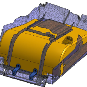
So I have created a cover for a model boat motor. I am very new to surfacing, so I'm sure there are better ways to accomplish this. I got roughly the shape that I'm after. At that point I'm actually just trying to thicken it to 5mm thick. I'm able to enclose it and turn it into a part without errors, but I can't get all of the surfaces to thicken without the errors. I know I don't need to enclose the surfaces if I can get the thicken to work. I just tried the enclose to see if any operation on the surfaces would work.
The URl to a copy of the document is below:
I assume it is related to the tangencies at a surface's edge, or maybe multiple edges. Any advice as to how to accomplish this would be greatly appreciated.
Tracy
Best Answers
-
 MDesign
Member Posts: 1,337 PRO
MDesign
Member Posts: 1,337 PRO
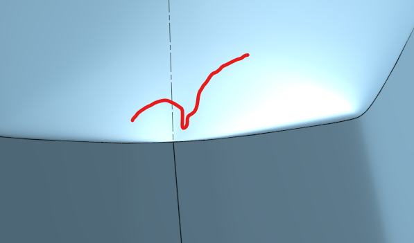
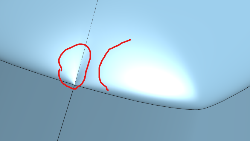
You can see where potential problems are with either the curve analysis tool (select a surface then shift+c) or for a quick check you can orient the lighting on the surface to see how smoothly it transitions across edges. here are two examples (there may be more) where its probably and issue for the thicken/shell operations. When the surface abrubtly changes from convex to concave you are almost always going to have issues.
0 -
 GregBrown
Member, Onshape Employees, csevp, pcbaevp Posts: 387
GregBrown
Member, Onshape Employees, csevp, pcbaevp Posts: 387 
Your Loft 3 feature has too much going on (too many boundary conditions) - trying to get the profile shape and the tight blends along the edge is not the “best practice”. I’ll take a look later when I get a chance. There are also some great learning center guides/tutorials out there for suggested surfacing practices. The primary one here will be to “build to theoretical sharps” then blend back in a second step….
0 -
MDesign
Member Posts: 1,337 PRO
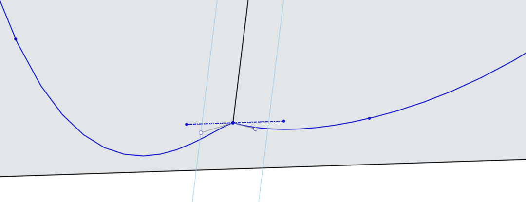
When your profiles intersect like this, its asking for troubles down the road as well. Set those magnitude lines colinear and/or tangent to related geometry and you'll have much cleaner surfaces from which to do operations like thicken as well. For reference this is on your very first sketch profile. Pay close attention to where those magnitude lines are or are not parallel, normal, tangent to other geometry to create smooth surfaces.
0
Answers
You can see where potential problems are with either the curve analysis tool (select a surface then shift+c) or for a quick check you can orient the lighting on the surface to see how smoothly it transitions across edges. here are two examples (there may be more) where its probably and issue for the thicken/shell operations. When the surface abrubtly changes from convex to concave you are almost always going to have issues.
Your Loft 3 feature has too much going on (too many boundary conditions) - trying to get the profile shape and the tight blends along the edge is not the “best practice”. I’ll take a look later when I get a chance. There are also some great learning center guides/tutorials out there for suggested surfacing practices. The primary one here will be to “build to theoretical sharps” then blend back in a second step….
When your profiles intersect like this, its asking for troubles down the road as well. Set those magnitude lines colinear and/or tangent to related geometry and you'll have much cleaner surfaces from which to do operations like thicken as well. For reference this is on your very first sketch profile. Pay close attention to where those magnitude lines are or are not parallel, normal, tangent to other geometry to create smooth surfaces.
Thanks for all the input. I think I need to get back to the basics and review more tutorials on surface modeling to build more foundational knowledge. Sorry to waste anyone's time when I haven't yet done enough homework on my own. I have already adjusted the shape in the master document, and I think I keep falling into the trap of starting too complicated geometry. I will try to simplify the shape first and then work up to the more complicated geometry.
Much appreciated, but let's close this thread for now. I'll keep learning.
These 2 are great places to start.
https://learn.onshape.com/learn/course/introduction-to-surfacing
https://learn.onshape.com/learn/course/onshape-surface-modeling
Thank you, MDesign!
Hello again folks, Thank you so much for pointing out the resources previously. I have spent a considerable amount of time in the learning resources and I've made a great deal of progress on this surface model and am almost there. What I have now would actually work functionally, but I am still struggling a bit to smooth the edges between my surface lofts on this model: (New Document)
https://cad.onshape.com/documents/d107c06dbf503282765211d4/w/dbdb6e2ef908dffa99f00337/e/105e3a3e38858a8ca2d9c5b0
Could anyone possibly give me some guidance on how to match the tangency, or possibly the curvatures between my lofts in this model? See image below for problem areas. It is where my loft edges meet. I can get the start profile conditions set with match tangency, which smooths the bottom edge of the lofts pretty well, but none of the end profile conditions work.
Do I need another pair of loft guide curves along the raised edges as shown below in green or something?
That's hard to see just from the pictures. I can not load your model (is is public?), but in such cases, a set of well placed guide curves may help. If you made this in several steps (as opposed to one big loft all over it), it might be worth while looking at the start and end conditions.
Sometimes, when the result comes out too much potato shaped, it helps creating a more defined looking surface, if the loft is done in portions. In this case this could mean to loft the two middle sections first. Once you have these and are satisfied with how the surface runs, then create the end caps with a tangent end condition. Trying to do all in one go usually introduces too many conditions to propely control.
And one more thing: If the part is symmetrical, only do one side and later mirror. That makes it easier. Use helper geometry to define tangency.
Sample:
https://cad.onshape.com/documents/9259412b987d2d79c19c4ec7/w/98c1b2f3f1ed3e1560cb0185/e/3d4357348a5897dc7843878e?renderMode=7&uiState=68de56503e22c53c084f3810
Thank you Martin, I'm sorry I had forgotten to make the document Public. I have now done that I you'd like to take another look. I did in fact model only one side as it is symmetrical across the centerline, but it is not symmetrical from front to back so I only mirror it across the centerline. I did use guidelines but I have a couple of wave like features running down each side of the part , thinking that it might add some rigidity.
I was also not able to get your document to load so I couldn't reference it. Again thank you for your suggestions, but I'm still a bit stuck trying to smooth the connection points between the individual surfaces.
My new public document is here:
https://cad.onshape.com/documents/d107c06dbf503282765211d4/w/dbdb6e2ef908dffa99f00337/e/105e3a3e38858a8ca2d9c5b0
BY JOVE, I THINK I'VE GOT IT! Thank you for guiding me along this path (pun intended). I added in a longitudinal guide for the individual lofts at the shoulder and the problem resolved in that area. I think I'll add another guide and I'll have a pretty reasonable surface. I still wish I could get the End Profile Conditions to work without erroring.
Zebra Curves don't look so great but at least I don't have distinct edges between my lofts along the shoulder where I added the shoulder guide any longer. I will try the last guide piercing my curves and see if that finally cleans it up. It would work as is, but I have to keep trying to get it clean.
Thank you folks, this is a great community!
Hi @tracy_fleming . Ooops, I probably moved the document to trash together with another after my experiment. Try again. It should work now.
https://cad.onshape.com/documents/9259412b987d2d79c19c4ec7/w/98c1b2f3f1ed3e1560cb0185/e/3d4357348a5897dc7843878e?renderMode=7&uiState=68de56503e22c53c084f3810
I also looked at your model. It works in principle, though it might help to avoid overstretched or self intersecting areas when you could put the profile sketches at an angle:
I edited your profile sketches slightly so the grooves run smoother and I took care of them having about the same number of vertex points, and added 'connections' between these in the center part of the loft. That makes everything look more parallel and more elegant. Also, I added tangency where the lofts meet at "Top Loft Guide" 1 and 2 .
There are, however issues with tangency in your basic sketches. These prevent the tangency in the loft to work accurately, for that forces the surface into a non-tangent edge at that point:
After adjusting that, it looks much smoother:
https://cad.onshape.com/documents/8d53fc6c0cf8c20d83a8d446/w/29201a0dbca767bf5025bb59/e/00d2623c73ff831a1334b999?renderMode=0&tangentEdgeStyle=1&uiState=68df9955b366198782fedcd1
Because of the somewhat overstretched surface (due to vertical profile sketches as mentioned above) there will be downstream issues e.g. when shelling the whole thing:
So it might be a good idea to rebuild these sketches and take care of a more relaxed surfacing all over. That Yamaha motor cover, however, does in fact consist of a load of distinct surfaces that have been built in a whole different manner.