Welcome to the Onshape forum! Ask questions and join in the discussions about everything Onshape.
First time visiting? Here are some places to start:- Looking for a certain topic? Check out the categories filter or use Search (upper right).
- Need support? Ask a question to our Community Support category.
- Please submit support tickets for bugs but you can request improvements in the Product Feedback category.
- Be respectful, on topic and if you see a problem, Flag it.
If you would like to contact our Community Manager personally, feel free to send a private message or an email.
designing big threads for manufacturing - help needed please
 rlbrk
Member Posts: 31 ✭
rlbrk
Member Posts: 31 ✭
Hello, Im designing a threaded body for manufacture, and I struggle with the thread design.
Usually, when making threaded parts, Im doing it for 3d printing and using the thread creator future script.
This is just one press of a button and I have a perfectly functional thread.
But for machining it, and for the manufacture to be able to do it precisely, Im not sure if this option is good.
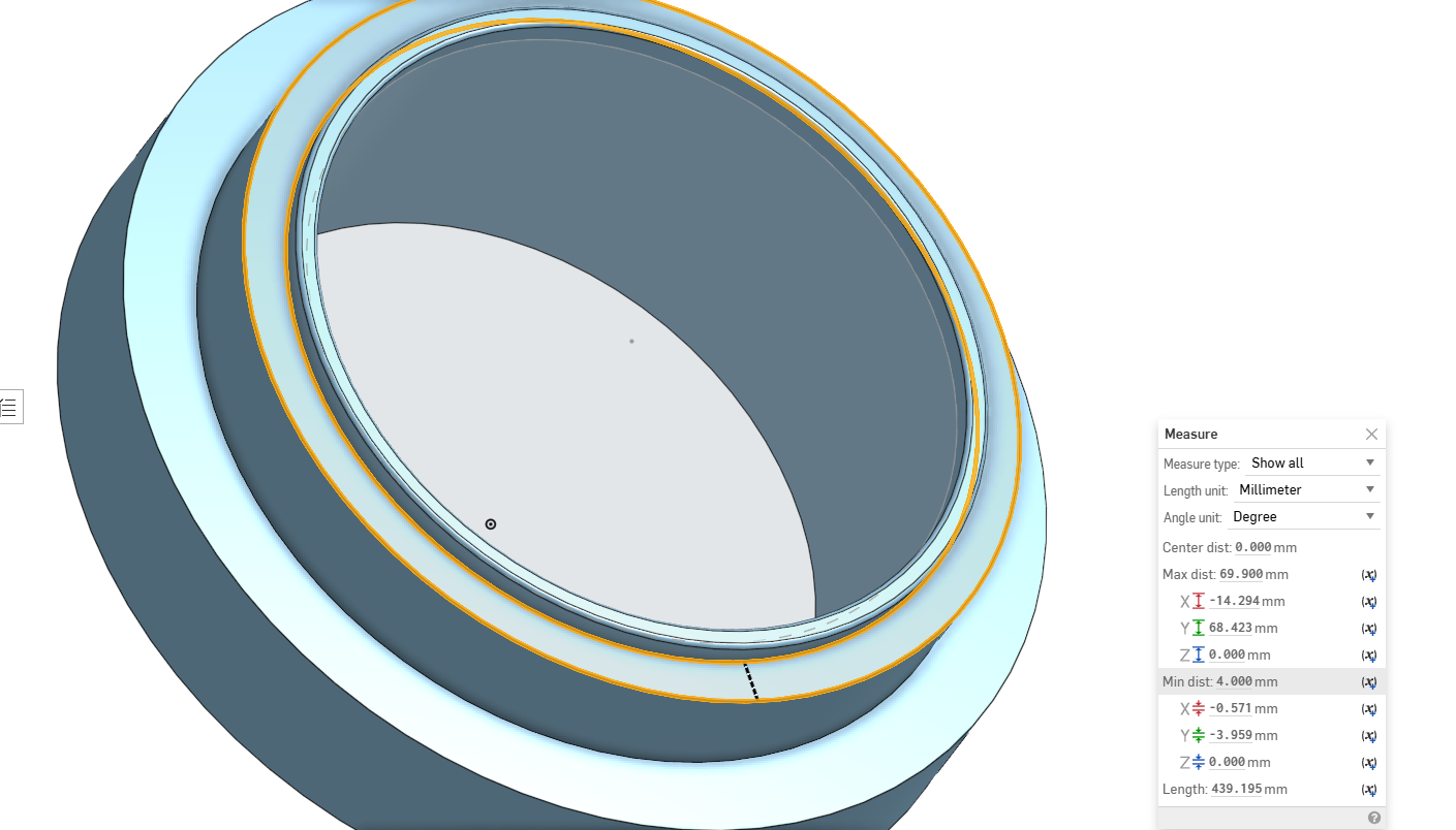
I need a way to make the top surface to stay at 4mm gap, like in the picture without the thread. When applying the thread creator, it is making the 4mm gap uneven through the circle.
What is the best option for me here? making it manually? It is important for me to keep the top surface gap 4mm. Is it even technically possible to be able to keep the gap even with a thread bellow it?
Thanks!
Comments
Probably need to do that with regular tools. Thread creator "removes" material and thus will make the top vary. You could add a small chamfer at the top to prevent it from cutting into the top but it would never thread on to something then since there'd be no entry spot for the mating thread. I'd say you want to create an external thread via helix and sweep. or create a "tool" piece with the female thread from thread creator that you can boolean subtract it from this piece shown.
Thread geometry is typically not modeled when sending parts to CNC or mass production companies. It's instead called out in a 2D drawing using standardized thread notations. Additionally, If this is something critical, you can show a section view of your part, where the thread starts and stops, etc.
1st: agree with Nick: don't model the thread if the CNC programmer can do it for you.
If you really need the 4mm top face to be precise, add a thicker area below it (Stepped with a chamfer?) and thread that.
Then you could still use thread creator.
Thanks, in the finished file it will be without the thread, but I have to make sure I get the surface above the thread to be 4mm. Do you think it is possible to crate the thread on the same diameter as the OD of the 4mm surface? (the diameter in the first picture) .
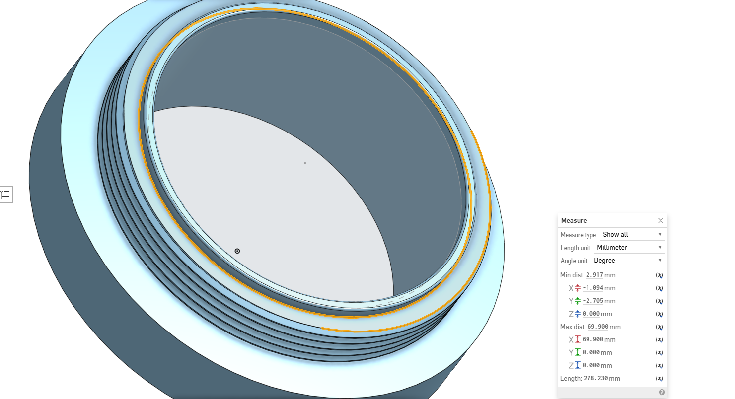
I think I'm looking for a thread like in the second picture, where the chamfer isn't removing material from the top surface of the bolt…
Do you think there is a way to make the thread diameter the same as the OD of the 4mm surface?
This is basically what Im looking for
if you remove thread from the OD of the 4mm surface, It'll always reduce the 4mm.
If you add it, it will also affect the top surface, because it will be wider at certain positions.
I would recommend this:
but your second picture with the chamfer directly at the surface also works as long as the chamfer is bigger than the thread depth obviously
Ok thanks, just want to point that I only need the top to be 4mm wide through all the cylinder, but the thread can take away material from underneath the top surface. Is it still impossible to have a full 4mm surface, and keep the thread diameter the same as the outer diameter of the 4mm cylinder?
Normally this won’t work.
How would the thread of the mating part engage with the thread below the 4mm rim? It wouldn’t be able to pass through to get to the cut thread.
Hopefully this image will show you why you can't do what you seem to be suggesting. There's no entry point for the mating thread to join this piece if you maintain 4mm with a cut thread. you have to add the thread to the outside of the 4 mm dia. and the thread needs to stop short of the 4mm area so as to not make that area wider.
Okay, so how can I achieve this chamfer thread in the picture so the top surface outer diameter will stay 4mm all the way from the inner diameter and the thread will stick out a bit?
This thread is just a picture I got, I didnt crate it myself
To get a chamfered lead-in for the threads like that, you need to create the chamfer using a revolved cut after the thread feature.
I usually make the profile sketch for the chamfer first, then add the threads, and finally do a revolved cut to make the chamfer.
Here is some screenshots of the steps.
As an aside, @robert_morris 's example can be 3D printed but will be difficult or impossible to machine either manually or by CNC because there is no thread relief at the bottom. The threading tool needs a bit of space between the last thread and the ledge to clear the ledge. Check with your machinist to see what he recommends. I typically will be a radial groove about 2 thread pitches at the ledge.
What you are asking for is not possible. A thread is a helix. If you were to take a screw from the hardware store and cut it in half, and then grind the end so it is very flat and smooth, it won't be a circle. It will be an elipse (or some other shape), because the thread wraps around it and climbs up.
It looks to me that you are making some sort of camera lens adapter or filter? And you want a shoulder to register onto a mating piece? The shoulder does not need to be a constant width for this to work.
Let me understand, The chamfer@robert_morris did is allowing the outer diameter at the top to keep the same distance from the inner diameter? (in my case the 4mm gap between the inner wall)
If yes, do you keep that chamfer on the model when preparing to send the files to the manufacture, or you point it out in the model drawing?
I'm still pretty confused on how to make sure the gap at the top stays the same, and if the special diameter of the threaded cylinder, 73.9mm, which isn't a standard size of diameter ( like M75 m76…) can be machine with a standard pitch, 3mm for example.
@michael3424
You are correct. What I showed is just an example showing the chamfer. For manufacturing I would definitely add a relief groove at the bottom of the threads.
@rlbrk
It depends on what you need. If you want a consistent circular edge where the chamfer begins, you should make sure the chamfer is larger than the depth of the thread cutter, and call out the size of the chamfer in the drawing. As Michael pointed out, you should also add a relief groove at the bottom of the thread for the tool cutter. Typically I don't show the threads in the drawing. I just have the outer profile with the chamfer and relief groove, and then call out the thread size in a note or with the external thread callout feature.
Your exmple in the pictures you added is what Im looking for. I want a consistent diameter on the top surface, so that chamfer allows it.
Now if I want to tell the manufacture to make that chamfer, should it only appear in the draw?
For example, M73.9 × 3 – 6g × 2 mm chamfer
Or I can leave it on the model and the machinist will just run the cutter through it?
Usually, the machinist will know to "undercut" a male thread that goes up to a shoulder ( common practice for single point turning of threads on a lathe ) - but I think you should include this information on the drawing. The level of detail you show in your model is a matter of personal preference - but 3d threads can clutter up a drawing very quickly.
I'd do it like this. And I'd communicate with the vendor on the phone/email/website your thread and chamfer intention.
The OD of the thread in the model is drawn at 73.9. The thread depth of a 3mm pitch thread is 1.62mm, so the chamfer and the thread relief are both drawn at 1.8mm depth to get under the root of the thread slightly. The only thing missing is the class of fit. Class of fit is often left off the drawing, but since you are making a bastard thread, you might want to look into it and include it. You can read more about metric thread profiles here: https://en.wikipedia.org/wiki/ISO_metric_screw_thread
That said, I'd recommend redesigning your part to use a standard thread. Bastard threads are the whole reason thread standards exist today.
The more I think about this, since it is a bastard thread, you might get a part back that doesn't fit the mating piece. How are you making the mating piece? You're asking for trouble IMO.
Link:
https://cad.onshape.com/documents/621f53690ea5d5952de4e674/v/a00ce01a946482581c09256e/e/4f49e78a6c0af208bc7cd02d