Welcome to the Onshape forum! Ask questions and join in the discussions about everything Onshape.
First time visiting? Here are some places to start:- Looking for a certain topic? Check out the categories filter or use Search (upper right).
- Need support? Ask a question to our Community Support category.
- Please submit support tickets for bugs but you can request improvements in the Product Feedback category.
- Be respectful, on topic and if you see a problem, Flag it.
If you would like to contact our Community Manager personally, feel free to send a private message or an email.
How to create a pyramid net
 c_byford
Member Posts: 2 ✭
c_byford
Member Posts: 2 ✭
Hi I'm complete newbie to CAD so please bear with! I've tried looking through the forums and tutorials but am probably not searching for the right term!
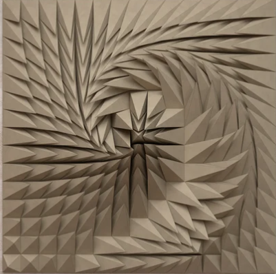
I'm a paper artist and have been commissioned to make something similar to this using various pyramid shapes.
I've worked out how to create the pyramids in Parts Studio but now need to 'unfold' it to create a net that that I can export a file so that my plotter can cut it. I assumed that the sheet metal function maybe an option but haven't seen anything obvious that creates what I need?
Here's the pyramid I've created - can anyone give idiot style next steps to create what I need?
Any and all help would be greatly appreciated
Answers
Cool pattern! Are you planning on creating a net that has ALL the pyramids in one? I'd expect overlapping faces in the unfolded net. Where would the pyramids (or the slabs they are the top of) be joined? I'd guess it'd be the easiest approach to make a configurable square base with a top that is driven by the coordinates of the tip point.
Run through this to learn the basics on sheet metal. that would help you a lot:
https://learn.onshape.com/courses/simultaneous-sheet-metal
Here I've tried to apply FS Node studio to generate this kind of pattern, there were few sharp moments but overall it did the work pretty good
https://cad.onshape.com/documents/149e0e4a805aa42734238e8c/w/b6b636962ff56f51fe0640cb/e/c77930bd90a3a36b573147d5
@Konst_Sh
This is very cool to see. Very much the type of things that Grasshopper users do all the time.
The next big steps would be generating the grid automatically (not with a sketch), how to easily add sliders (configuration variables?) to drive the grid density and the power of the attractor to modify the pyramid.
@c_byford
You might want to look at @EvanReese 's Attractor Pattern FS which can do a lot of cool things without any coding, but as far as I can tell, can't quite do what you want the way Konstantin Shiriazdanov's script is starting to do. Perhaps you can learn a bit from both approaches.
@EvanReese
I hope you get a chance to redo the video for Attractor Pattern.
Simon Gatrall | Product Development, Engineering, Design, Onshape | Ex- IDEO, PCH, Unagi, Carbon | LinkedIn
A couple questions: Can you make single pyramids? Or must all the pyramids start as one giant sheet of material? As far as I can tell, both are possible, but single pyramids will be a lot easier.
I think it would be very, very hard to get the sheet metal tools in Onshape able to do this 'for you', the way you want. But because the pyramidal shapes are quite easy, you might not need to.
I tried doing this just based on sketches. I made the following constraints/observations:
1. Once the pyramids are folded, their base edges must touch and match the next pyramids edge - because they are the same edge. The base edge segments for a single pyramid are circled in blue. See how they touch the base of the pyramid next door?
2. The height of the pyramid (in your picture, coming out of the screen) can't be fixed. The material available for each pyramid, however is fixed (as a square larger than the pyramid base). Here, you see the 4 triangles that make up the vertical walls of each pyramid. So that means pyramid height will vary as you move the tip of the pyramids around.
3. On the right, you see a blue square? That's where I can change the "pyramid tip position" to get different patterns. By moving the point around inside this shape and building my triangles I can get different shapes
See the tip positions? Still inside the smaller square in the preceding images (i just turned off that sketch because it was hard to read):
4. The material you dont want to be in the pyramid has to be folded out of view. That appears to work out fine, actually. The black lines down the center of the triangles that arent making pyramid walls are the guidelines for the fold that tucks that inner material away. It's where you fold the paper and the adjoining pyramid side walls come together properly. Here is the shared edge between two different panels that are going to be touching in the final result, so they must come together.
Anyhow, it seems possible to do this with a simple (albeit busy) sketch, a drawing (you can insert your sketch in to a drawing element and then scale it there if you need to. For example the folded version drawing is 2:1.
After a lot of folding:
And yes I know my folding is an abomination, apologies. But the tip locations make sense w.r.t to the flat pattern on screen (upper right → an upper right pointing pyramid, like my top-left pyramid in the quad).
A couple observations:
1. I discovered that small changes in the tip position lead to big changes in the resulting pyramid, and I think that's because my "starting material" square is not much bigger than my pyramid base, so there's a relationship there to watch out for.
2. I could get the "Flatten surfaces" utility to work but it wasn't very helpful tbh. No one can find it though so fyi it's under the protractor menu in lower right corner here. This isn't the sheet metal tool, just an approximation, but it's pretty rad. For regeneration you aren't allowed to "commit the feature" so if you use this tool, export it as a solid and reimport to a different tab.
I really don't know if this will be of help to you but wanted to show you a way I kind of got something to work. Maybe it will help!
https://cad.onshape.com/documents/b747563b4feb54ce37edc7d7/w/b28f6675ccd215516d1305c4/e/ba17d67d290110b157c417c1
@S1mon thanks, sure its possible to create regular grids with some sketch line patterning, though the approach when the grid is created idependently has its benefits actually - you can have non planar, or non adjacent facets of arbitrary shape. The more interesting area here is the attraction strategy itself, currently its just vector from centroid of the facet to closest attractor point, but clamped to some max value, however it could be more interesting
The problem here is some pyramid tip points are outside of the projected area of the base square. That will lead to self-intersections in the flat pattern and prevent the use of the shee metal toolset. There will be single pyramids or maybe small groups of pyramids at places.
I've seen videos from artists doing similar sculptures where they create a series of cones/pyramids/spikes that flow similar to this out of various materials. They make the final assembly from individual parts that are attached to a baseplate. As long as you have a good system for numbering the parts, this seems pretty manageable, and perhaps easier that trying to make everything in one piece. There are too many things that would all have to go right in order for that one part to look/work right. Each individual pyramid will be a relatively simple part that is much easier to redo or replace if something doesn't quite go right.
Simon Gatrall | Product Development, Engineering, Design, Onshape | Ex- IDEO, PCH, Unagi, Carbon | LinkedIn
This reminds me of something I made back in 2015 using Rhino/Grasshopper, and X-acto, and a bunch of hand cramps.
You can get to something similar in Onshape. Here's an example: https://cad.onshape.com/documents/15d45eb42a9fa95ad82df5be/w/ef1285a63adb32b9dde86a3c/e/0fd298a780ed9d412ba7a010
Challenges I didn't yet overcome are:
Relative skill-levels treated as equal, Grasshopper is a better tool for this, but Onshape can work.
The Onsherpa | Reach peak Onshape productivity
www.theonsherpa.com