Welcome to the Onshape forum! Ask questions and join in the discussions about everything Onshape.
First time visiting? Here are some places to start:- Looking for a certain topic? Check out the categories filter or use Search (upper right).
- Need support? Ask a question to our Community Support category.
- Please submit support tickets for bugs but you can request improvements in the Product Feedback category.
- Be respectful, on topic and if you see a problem, Flag it.
If you would like to contact our Community Manager personally, feel free to send a private message or an email.
Help with Creating a Drawing for a Part to Be Machined – Newbie

Hi,
I’ve designed a part that I’d like to send to a CNC service. This is my first time preparing a drawing for manufacturing, so I’m not entirely sure about the correct format or how the manufacturer prefers to receive it. I want to make sure I don’t send something they might reject or find difficult to work with.
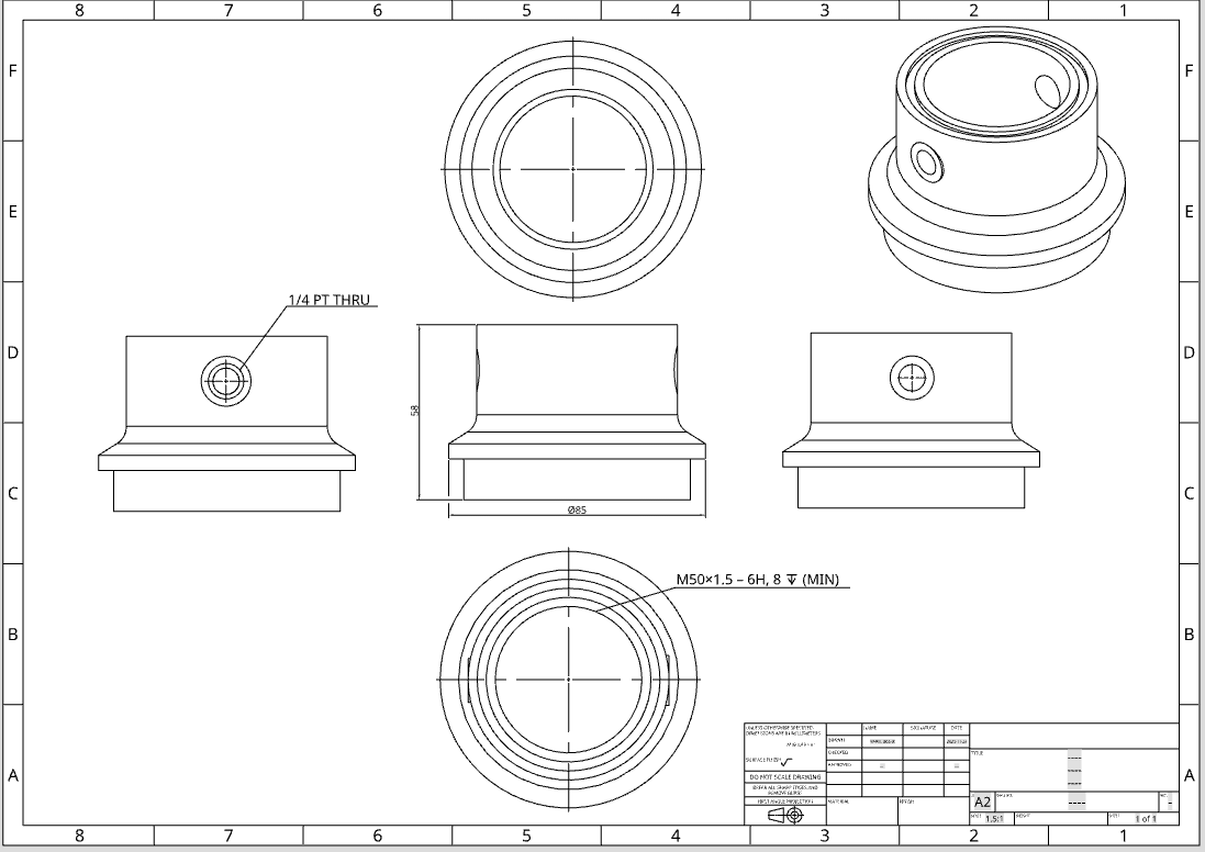
I’ve attached an image of the drawing I’ve created so far. I followed a video explaining how to align the different faces using first-angle projection. The part requires thread callouts only on the sides, top, and bottom. I have included five views: front, top, bottom, right, and left, and aligned them as shown in the reference from the video. I haven’t added all the thread callouts yet, and I also want to include a section view for the bore.
Would it be acceptable to send the drawing in this state? The bottom face seems small, so I’m wondering if I could rearrange the views by placing the right-side view below the front view to save space. Also, should I model chamfers on the sharp edges, or is it sufficient to note “deburr all sharp edges” in the drawing?
I apologize for the basic questions, as this is my first time handling this, and I need the part as soon as possible.
Thanks
Comments
On order to create an engineering drawing for the manufacture of a part you need to provide all the dimensions the machinist would need to produce that part.
The layout of your views and the number of views are important.
Q: How many views should my drawing have?
A: As few as you can get away with.
For example if the top view of the part shows no extra information than the bottom of the part, pick one.
In a similar vein. Dimension things once and only once. The height in one view will be the same as the height on the next view. Do not dimension it twice.
Q: Where should the views go?
A: Depends.
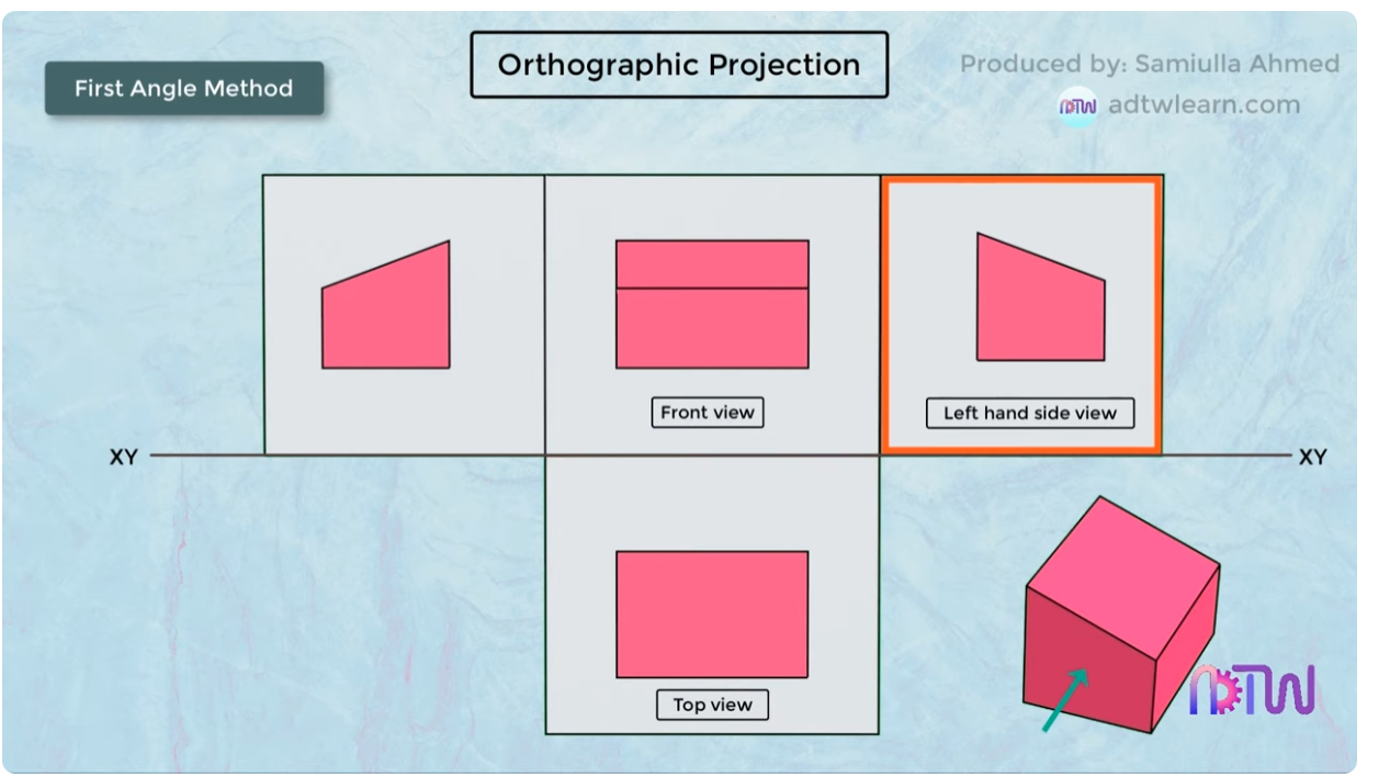
1st angle projection.
Imagine that your three dimensional solid object (say your phone) is sat on top of your piece of paper (screen up, inviting you to doom scroll). Without removing your phone from the paper lift it so you can see the bottom of your phone. Note that even though you are looking at the bottom of your phone, your phone is at the top of your piece of paper.
This is first angle orthographic projection. It's bassackwards.
3rd angle projection
Repeat the above but with your phone underneath a sheet of tracing paper. You can also imagine your phone moving around inside a large mixing bowl.
Note that when your phone is at the bottom of your sheet of paper you can see the bottom of your phone.
Do not mix these up in the same drawing. It confuses people.
Onshape will lay the views out correctly one with the template settings you used.
Looking at your drawing there is a lack of dimensions. Would you be able to model the part from the dimensions given?
I would, i think, only use three views. Center, bottom, and left, or right (not both, they provide the same info). You might need hidden detail on the center.
And yes. Model the chamfers.