Welcome to the Onshape forum! Ask questions and join in the discussions about everything Onshape.
First time visiting? Here are some places to start:- Looking for a certain topic? Check out the categories filter or use Search (upper right).
- Need support? Ask a question to our Community Support category.
- Please submit support tickets for bugs but you can request improvements in the Product Feedback category.
- Be respectful, on topic and if you see a problem, Flag it.
If you would like to contact our Community Manager personally, feel free to send a private message or an email.
Angled spars through ribs
 graham_lock
Member Posts: 265 PRO
graham_lock
Member Posts: 265 PRO
Hi all,
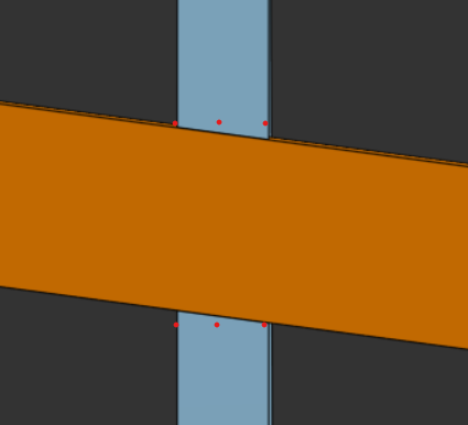
I have a spar (orange) which is notched into ribs (blue).
The spar is not perpendicular to the ribs and so the notches in the ribs have angled faces.
The ribs will be cut by 2D laser cutter so it is not possible to cut those angled faces.
The notch faces would need to follow the red dots in the image below.
The spar may have twist so it's not guaranteed to be possible to place a sketch plane on its upper surface to extrude a rectangle for example.
I've played with point planes which allow me to setup planes where the red dots are but then there's extra work to tidy up the ribs below the spar since the resultant notch must only be as deep as the spar.
Ultimately I want to create these notches in FeatureScript but I need to see a sensible (simple) way of creating them manually first.
Any ideas on how best to achieve this appreciated.
Thank you.
Answers
I have the core essence of a solution to this in 456D Make but I haven't yet enabled the non-perpendicular ribs cases or independent control of plane spacing. What I'm doing in the script is projecting the non-normal wall faces back to the primary and then thickening them the slice width and removing the geometry to normalize the cuts. Future updates will include skew slicing support.
So essentially I'm doing a Boolean intersection (actually subtract_complement for ID stability reasons) between the two members, splitting that body in half along the pull direction, and Booleaning each half of the intersection with one of the slices, letting the faces be skew.
Then apply a normalization script that does the project>thicken>remove process. It handles simple geometry extremely well, more complex geometry so-so.
Derek Van Allen | Engineering Consultant | MeddlerThanks @Derek_Van_Allen_BD
Taking your description and trying to turn it into a FS script workflow:
is that pretty much what you were describing?
Thank you.
Philosophically more or less. Minor differences in my implementation. Firstly I'm picking a primary face on my ribs that already exists to project to instead of trying to go middle out. Secondly I'm using a function called opCreateOutline instead of creating a sketch for my projection method. Thirdly I chose to use opThicken instead of an extrude. The core reasoning for this is that sketch geometry constrains you to planar geometry and there's a world where I want to normalize a rolled surface. All of these functions should be applicable to a curved domain instead of pigeonholing my script to only work in flat land.
Derek Van Allen | Engineering Consultant | Meddlerok thank you, I haven’t come across opCreateOutline, I’ll have a play.