Welcome to the Onshape forum! Ask questions and join in the discussions about everything Onshape.
First time visiting? Here are some places to start:- Looking for a certain topic? Check out the categories filter or use Search (upper right).
- Need support? Ask a question to our Community Support category.
- Please submit support tickets for bugs but you can request improvements in the Product Feedback category.
- Be respectful, on topic and if you see a problem, Flag it.
If you would like to contact our Community Manager personally, feel free to send a private message or an email.
How do I retain a negative measured variable?
 RhettRobinson
Member Posts: 196 ✭✭✭
RhettRobinson
Member Posts: 196 ✭✭✭
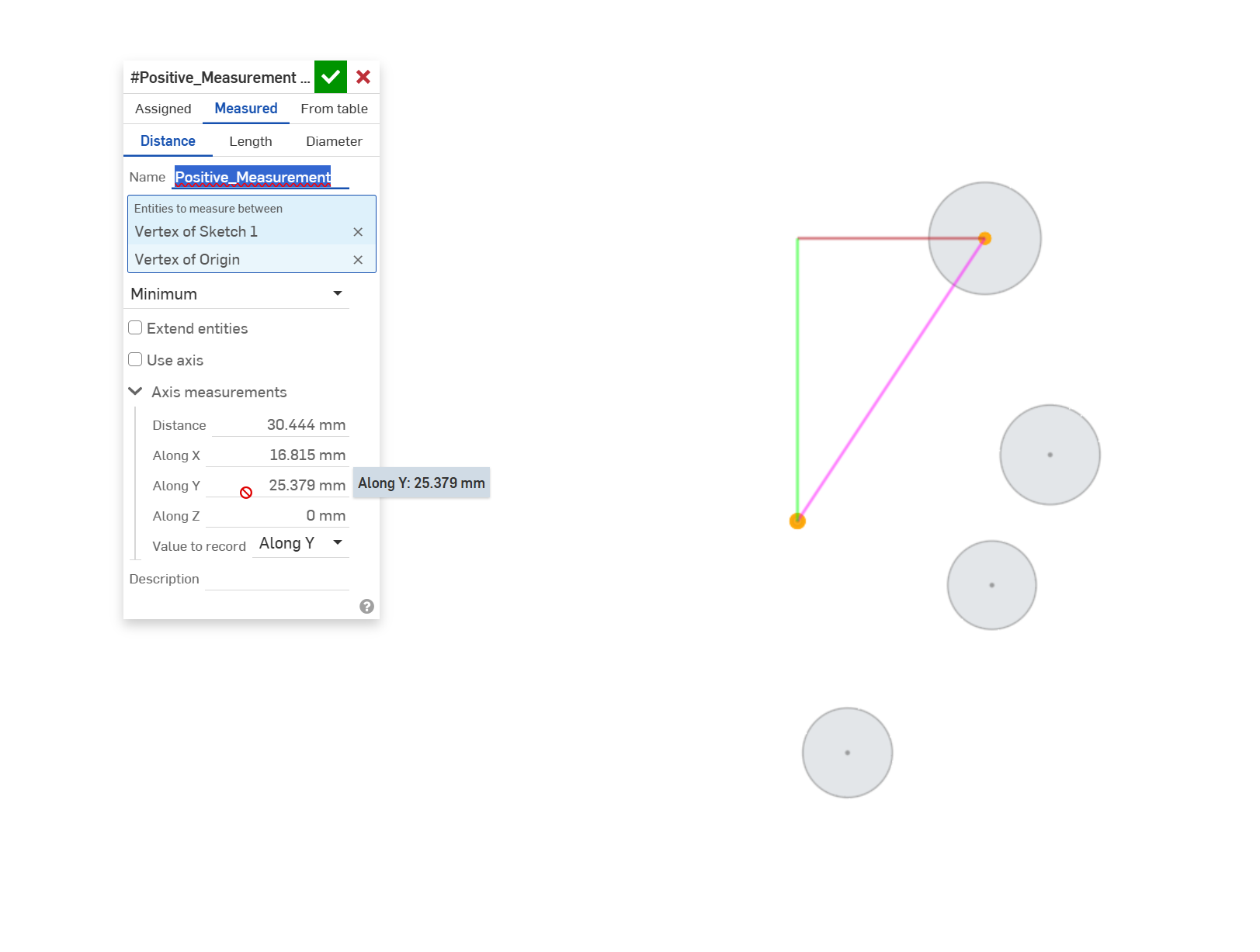
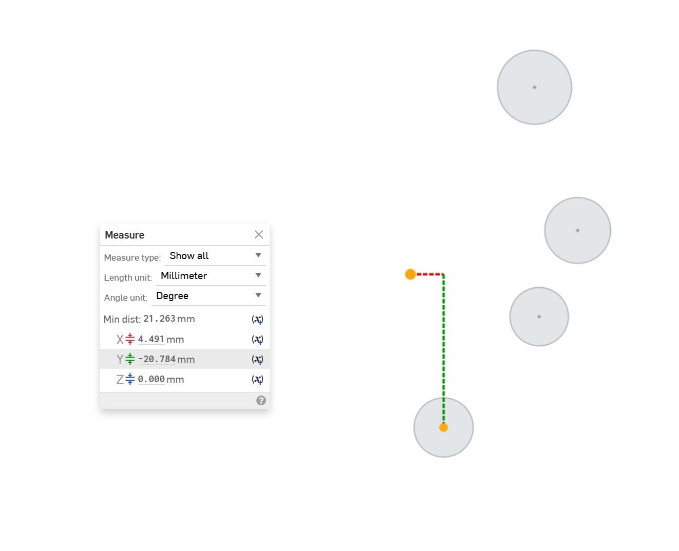
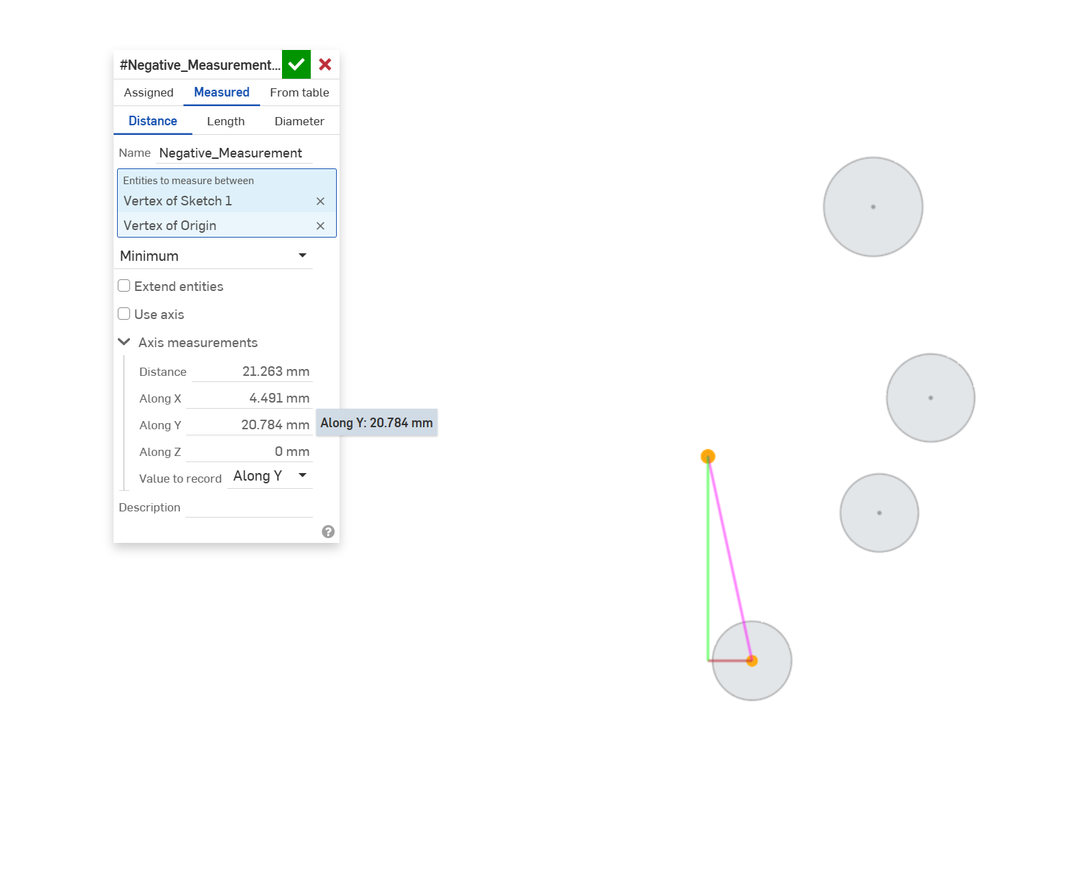
I am working through a process that requires the calculation of the distance along the global Y axis of sketch entities (in this example the center of circles) from the origin all on the same plane within a sketch. It is very important that I retain the positive or negative value. You can see from my images below that if I measure from the center of any of the circles to the origin (selected in that order) that I will get a positive or negative value. However, once I select measured variable the negative sign disappears. I am hoping to run this through some other features like Query Pattern, but without retaining the -Y measurements it doesn't work properly.
Answers
Long time no see 😎 Measure Mate to be able to do this. It can also handle angles with signs as well.
I just updated
.
RENDERCAD
rendercad.ai - Photorealistic product rendering.
▚▞▚▞▚▞▚▞▚
________________________________________________________________________
Seriously 😂
Brilliant, taking it a step further can you update it to allow mate connectors to also be selected in the entities box? 😁I should have actually shown that in my example.
@MichaelPascoe So I should have waited to reply, this doesn't look like it is doing quite what I need. 😔 Are vertices and mate connectors not available options as entities for selection?
There you go, I added it. Was a really simple change.
.
RENDERCAD
rendercad.ai - Photorealistic product rendering.
▚▞▚▞▚▞▚▞▚
________________________________________________________________________
Maybe I am not understanding how to set it up properly, I don't seem to be getting a negative measurement in the y direction now that I have pulled in your update. I have tried both points or mate connectors in flipped order and it is still positive.
Distance measurement sign is based on the input mate's xy plane, see the example tab in the document. That said, it still might not be what your going for, not sure yet.
RENDERCAD
rendercad.ai - Photorealistic product rendering.
▚▞▚▞▚▞▚▞▚
________________________________________________________________________
Here is some code I pieced together (I need to brush up again on my fundamentals) that is giving me what I need. All I really want now is to code in the debug lines as shown in my markup and make the value fill into the name of the feature. Pretty stripped down, but that's all I need it for.
Ok, to auto name the feature based on your measurements you will need to put this in the header:
And then set that computed parameter in the feature body:
To create a debug line, use this method:
.
RENDERCAD
rendercad.ai - Photorealistic product rendering.
▚▞▚▞▚▞▚▞▚
________________________________________________________________________