Welcome to the Onshape forum! Ask questions and join in the discussions about everything Onshape.
First time visiting? Here are some places to start:- Looking for a certain topic? Check out the categories filter or use Search (upper right).
- Need support? Ask a question to our Community Support category.
- Please submit support tickets for bugs but you can request improvements in the Product Feedback category.
- Be respectful, on topic and if you see a problem, Flag it.
If you would like to contact our Community Manager personally, feel free to send a private message or an email.
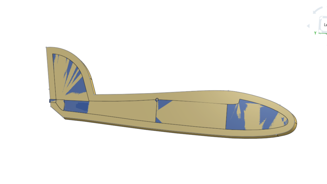
What's going on here....is the "flat" back of loft is concave?
 jim_zamecnik
Member Posts: 23 ✭
jim_zamecnik
Member Posts: 23 ✭
I'm working on turning this fuselage model into a 2-piece mold. When I tried to do a Boolean Subtract to create the mold half, I got a non-manifold failure. Looking at the color interference pattern it seemed like the back of the fuselage loft was concave. I moved the sketch plane (17) over by 0.5mm and the subtract succeeded, but I got these weird floating bodies (color added for emphasis). I had to offset that sketch plane 2.5mm to get rid of them entirely. Which ruins the model, especially the tail fin. What's the cure?
I also tried mirroring the fuselage but that failed too, probably for the same reason.
https://cad.onshape.com/documents/da3de3372533e1e3b63d6c6d/w/c1f29e0ed682767a43c2f25a/e/42eaec421bc37ab77d36eafc?renderMode=0&uiState=69a4da3cb8618a4eb4d42140
Comments
Looks like the loft method is drawing the face in at those areas that look flat by eye, You may need to add guides/? to hold those surfaces flat.
https://cad.onshape.com/documents/2815dbd86b73c56a2ef6b16c/w/0c50e79adbba355399136004/e/dc7e42b3e3d41e76e15e930d
@jim_zamecnik
I'm sorry but …
To make it short: Your modeling is too dirty for booleans to work. It is not only the concave backside, it is in every detail. Nothing really matches. Here's one sample with a debris field of minute faces selected that aren't needed, belong nowhere, but spoil all math:
Many of that needs to be rebuilt. Maybe the result is just enough for the milling, since the details are too small to be milled anyway, so here it goes:
https://cad.onshape.com/documents/8229f34fc507f18e6c490e49/w/91c73a57af3f9e62016fcc92/e/ec36057021a0774982f9bdc9?renderMode=0&uiState=69a575b55941095f9df7834f
I know my people has a reputation for being blunt at times. It's not exactly true. Just not beating around the bush. So, instead of fixing all the details, now you figured out the general shape of things, I'd just start from scratch, build it in a structured manner, make it right from the beginning.
Thanks guys, I really do appreciate the advice. And the criticism.…that's how we learn, right? I know this project is a totally disorganized mess. My very first attempt at 3D CAD. I've been down a lot of dead ends figuring out what works (and what doesn't!). I'm learning in what order things need to be done and how they need to be connected.
But....I found a fix myself last night just after posting my question. (I wasn't able to come right back and mention it, because of the long lag between submitting a post here and when it shows up on the forum. Why is that?) I used a series of Replace Face commands to flatten those loft surfaces on the back, and the Boolean and Mirror commands worked perfectly :-)
Onward.... I need to cut this thing up so it can be printed in pieces then reassembled accurately. And some alignment keys in the mold halves.
And thanks Glen, guides are are on the (long) list of things I need to learn more about.
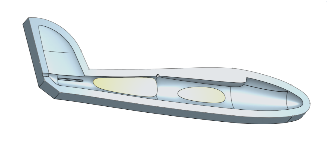
Hey Jim.
Spent a little time going over methods to get the inside face of fuselage level. There are no left over bits or voids along the center plane when mirrored You'll note that the main fuselage is done in one loft instead of multiple lofts that come together much smoother with loft guides. The next loft sets a criteria of normal to sketch with a start and end magnitude large enough to allow for an inside radius that won't collapse in on it's self when shelled. You may want to go over some of the the training examples. There are some unnecessary planes where selecting an implicit point on existing geometry will give the start coordinates for sketching. Some times it's worth going back to start when the feature tree get messy and you have figured out what works best. Keeping a well structured feature tree will make updates latter a lot less confusing.
Also, crisp clean edges on things like a trailing edge don't work well with shell or thicken. They will fold in on them selves and fail. While this takes a bit of time it will give you the time back multifold. https://learn.onshape.com/?hostDomain=cad
Cheers Glen 🙃
https://cad.onshape.com/documents/2815dbd86b73c56a2ef6b16c/w/0c50e79adbba355399136004/e/dc7e42b3e3d41e76e15e930d
BTW. After getting some library errors from OS I went for the document update and the problems went away.