Welcome to the Onshape forum! Ask questions and join in the discussions about everything Onshape.
First time visiting? Here are some places to start:- Looking for a certain topic? Check out the categories filter or use Search (upper right).
- Need support? Ask a question to our Community Support category.
- Please submit support tickets for bugs but you can request improvements in the Product Feedback category.
- Be respectful, on topic and if you see a problem, Flag it.
If you would like to contact our Community Manager personally, feel free to send a private message or an email.
Newbie Question: Still trying to make that JST connector in the panel wall
 varocketry
Member Posts: 12 ✭
varocketry
Member Posts: 12 ✭
Okay, I gave up on the SHELL command.
I've created the box I needed off model and got it where I think it should be.
I move it (transform) onto the panel wall where it should be located. It appears there mostly fine EXCEPT the wire slot Extrude-Remove won't Remove the panel wall in the opening, despite every attempt I've made.
Can someone advise me?
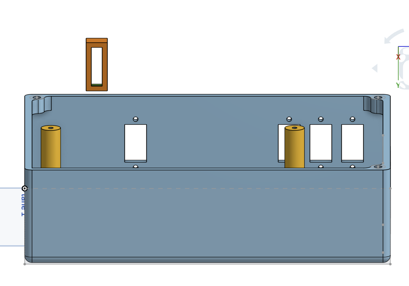
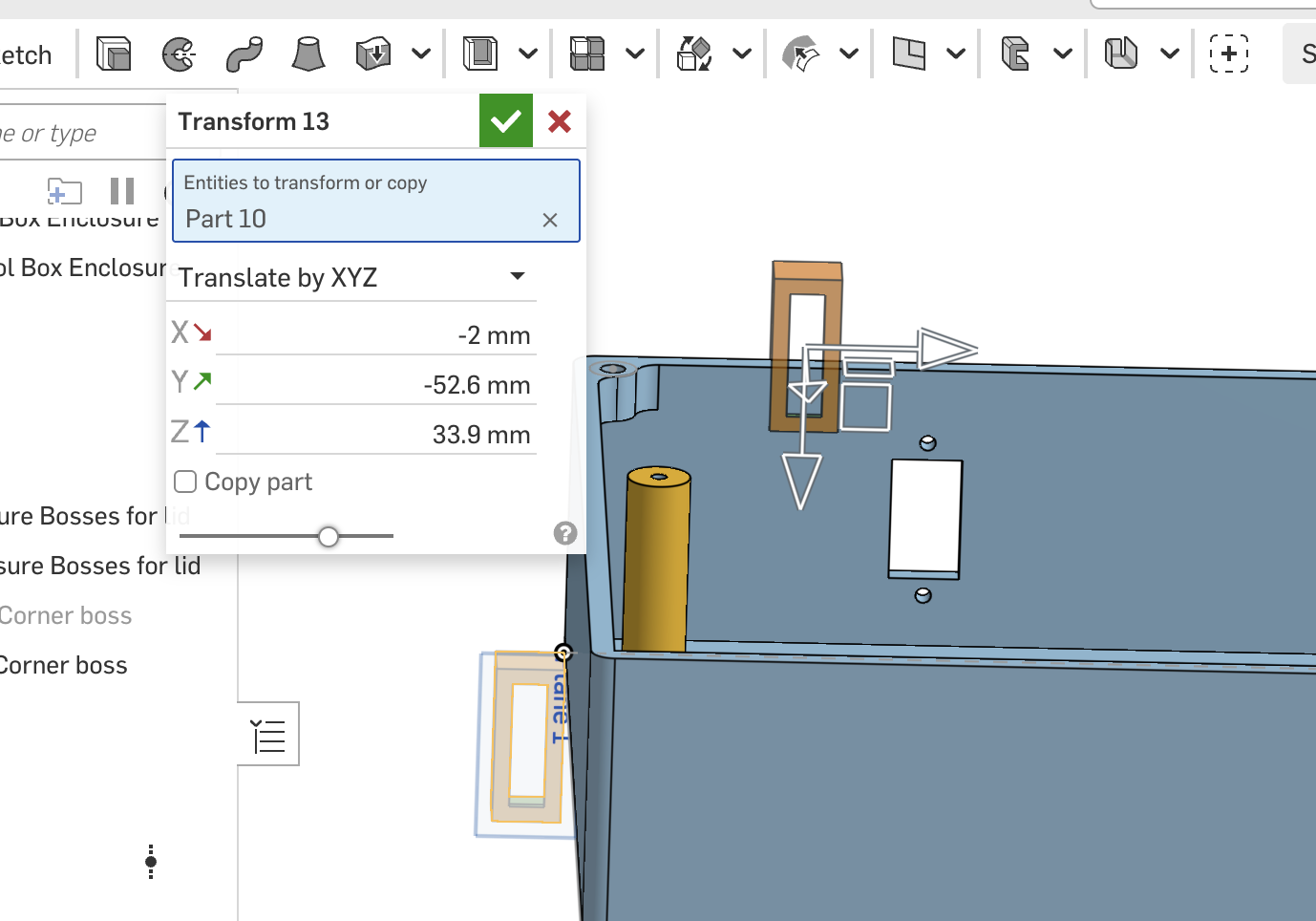
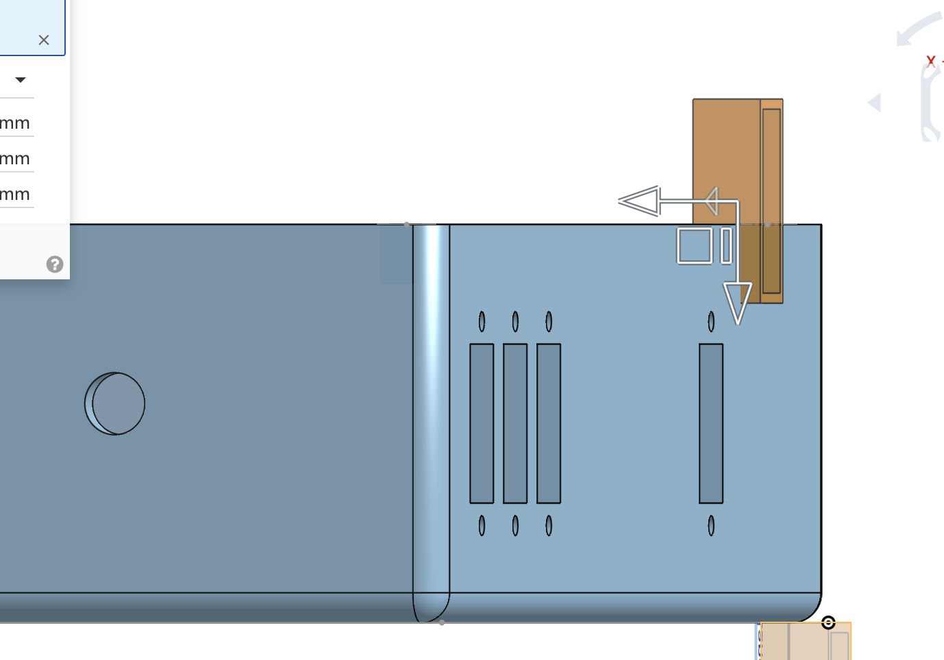
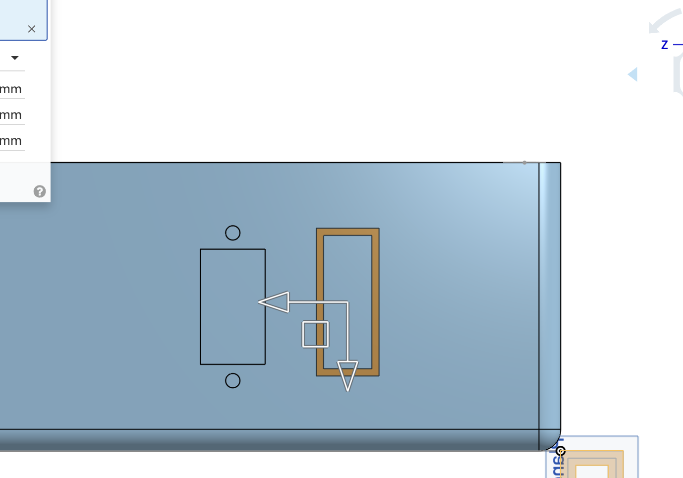
Thanks in advance for helpful suggestions.
Tagged:
0
Answers
Looks like the tool you need is Boolean Subtract. You're going to end up with an extra part due to the tool (the rectangle extrusion) being hollow. Just delete the extra center piece. - Scotty
Robert:
Can I merge that newly formed part with the box?
Yes, sounds a bit silly since you used a Boolean Subtract to create the opening, you can use a Boolean Union to join the parts. I think a better approach would have been to create a sketch on the face where the hole is meant to be. With the sketch, you would have control over its position via dimensions and perhaps constraints. From there an Extrude Remove could create the hole and the same rectangle used to create the hole could be Extruded Thin to create that surrounding JST shell. - Scotty
Scotty:
That's exactly what I originally did. And when I did that, the enclosure box's walls mysteriously became HOLLOW instead of th original solid walls. SO I entered a quesiton was that behavior a BUG.
I was told that my use of the 2nd SHELL command was incorrect.
But noone has described how to do it correctly.
Support tried and sent me examples - and I pointed out to him that the walls of the box turned hollow IN HIS EXAMPLE, if he looked carefully at his diagram.
No answer to that that I've received.
My attempt to add the structure and add it to the original box has failed in printing and that new part wasn't actually added to the enclosure's walls.
So Newbie me is at a loss here.
No doubt you're disappointed and frustrated. Can you please post a link to your document?
By the way, what are you making? What is the purpose of the box?
- Scotty
Im with the others. If you are trying to make a rectangular opening with a wall pointing inward, all you need is a rectangle sketch. Use it to cut using the extrude feature. Then use it again in a second extrude feature as a thin extrude to get the wall.
I went through your model. You've made good progress for being a newbie:) Some suggestions for you:
Stop using transform! You must have moved the pcb 15 times back and forth. Draw the pcb in place, not at the origin like you did. I feel you are transforming it back and forth to see under it. Use the hide part command instead.
You also used transform a bunch of other times to move the battery box and to move the JST connector cut and probably other stuff I'm forgetting now. That's not what it's for. Draw them where they belong from the start. Don't draw them in a random place then try to transform them where you want them.
Start using the assembly studio. The battery box and batteries (I'm assuming it's off-the-shelf and will be part of an assembly…) belongs in the assembly, not the part studio. When you start populating all the other off-the-shelf stuff such as the connectors, screws, etc, they all belong in the assembly. If you are coming from Fusion 360, it's not like that. (If the battery box will be printed one piece into this design, then I take that back and the battery box does belong in the part studio).
Draw your root box shape centered about the origin. Not with its corner at the origin.
Do the major features of the box first, which are the main portion, the lid, then the bottom. You did the main portion and the lid first. Then put all the tiny details inside, including ribs for the bosses that ended up floating in mid air. Then you tried to split the bottom off. A design like this make the basic box, then shell it, then split it twice for the lid and the bottom. Then make the bosses to connect all 3. Then, do all the small details inside the box for the pcb, connectors, etc.
Sketches need work. You don't know what equal constrains are, and you are dimensioning each hole individually when they should all be the same.
You can reuse the same sketch for multiple features. The bosses for the main portion you made a sketch to locate them and for their diameter. Then you made a brand new sketch for the bosses that go on the lid, locating them from the corners of the box, rather than coincident from the prior bosses they screw into.
His model for anyone else (link was shared from his other thread): https://cad.onshape.com/documents/04fe34b82f39341467d674d2/w/5318fa305465743b80830d34/e/3ad79005b19d36266699c117