Welcome to the Onshape forum! Ask questions and join in the discussions about everything Onshape.
First time visiting? Here are some places to start:- Looking for a certain topic? Check out the categories filter or use Search (upper right).
- Need support? Ask a question to our Community Support category.
- Please submit support tickets for bugs but you can request improvements in the Product Feedback category.
- Be respectful, on topic and if you see a problem, Flag it.
If you would like to contact our Community Manager personally, feel free to send a private message or an email.
Making models that use intersection and loft more robusts
 Xavier_3
Member Posts: 6 ✭✭
Xavier_3
Member Posts: 6 ✭✭
Hi,
I'm trying to model some tubing joinery to make a basic triangular stool (From a triangular seating board, tubing & string). My goal is to model the feet and the seat joinery (Each foot links two tubes and a rope. Top joints link two tubes, a rope and a board corner).
Model: https://cad.onshape.com/documents/ec12dd36f550c3f2d2b4dcca/v/b6943f05bfda7ee2484ab1b0

I'm having a hard time being robust and precise with the joinery modelling. I would want my model to be robust enough for me to be able to resize the tubing diameter without breaking the model.
My idea to design the feet (And the upper joint) was to design some sleeves around the legs, then intersect the sleeves with the ground and my feet upper plane to get two surfaces than I would then loft.
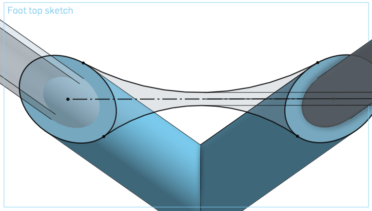
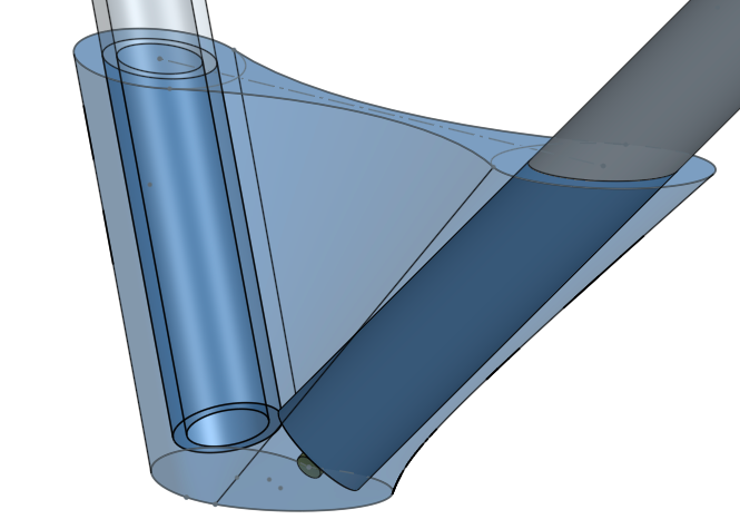
It works more or less but it doesn't seem to be super robust. I had to redo it from scratch multiple times and as soon as I change my tubing diameter variable it breaks either my intersected sketch, either the lofting.
Would you stick to this modelling approach or would you have tried a different way?
Model: https://cad.onshape.com/documents/ec12dd36f550c3f2d2b4dcca/v/b6943f05bfda7ee2484ab1b0
I'm trying to model some tubing joinery to make a basic triangular stool (From a triangular seating board, tubing & string). My goal is to model the feet and the seat joinery (Each foot links two tubes and a rope. Top joints link two tubes, a rope and a board corner).
Model: https://cad.onshape.com/documents/ec12dd36f550c3f2d2b4dcca/v/b6943f05bfda7ee2484ab1b0
I'm having a hard time being robust and precise with the joinery modelling. I would want my model to be robust enough for me to be able to resize the tubing diameter without breaking the model.
My idea to design the feet (And the upper joint) was to design some sleeves around the legs, then intersect the sleeves with the ground and my feet upper plane to get two surfaces than I would then loft.
It works more or less but it doesn't seem to be super robust. I had to redo it from scratch multiple times and as soon as I change my tubing diameter variable it breaks either my intersected sketch, either the lofting.
Would you stick to this modelling approach or would you have tried a different way?
Model: https://cad.onshape.com/documents/ec12dd36f550c3f2d2b4dcca/v/b6943f05bfda7ee2484ab1b0
2
Answers
Since your doc is read-only, I can't really interrogate it deeply enough to diagnose what the specific problem might be, but I can make a suggestion: keep your reference hierarchy "flat and wide".
By that I mean that if A is referenced by B is referenced by C is referenced by D is referenced by E, (A > B > C > D ), your rebuild reliability goes down with each consecutive layer. If you can, it's better to keep those relationships "flat", e.g. A > B, A > C, A > D. This way all of your other features (B, C, and D) reference a single feature (A), and if any one of them were to break, the others will be unaffected.
This strategy is helpful in a number of ways.
So in your case--again, without seeing exactly how you're doing it--I would consider creating a master cylinder extrude for each leg of the table as a sheet body (not a solid), and then building all of the other components using that as a reference. The legs would be thickened versions of the sheet. The blue foot would reference the sheet directly instead of referencing the thickened legs, etc. This way you have a single source of truth ("A" = the master cylinder extrude) and a bunch of completely independent children (legs, foot barrels, etc).
I realize that's abstract, but I hope it's helpful.
Original model: https://cad.onshape.com/documents/ec12dd36f550c3f2d2b4dcca
It's hard for me to be more specific about your model because Onshape doesn't currently give us a way of knowing what each of your features does unless we have write-access to the model. With read-only access, all I see is your feature names, but I don't know if they're extrusions, sweeps, thickens, or whatever.