Welcome to the Onshape forum! Ask questions and join in the discussions about everything Onshape.
First time visiting? Here are some places to start:- Looking for a certain topic? Check out the categories filter or use Search (upper right).
- Need support? Ask a question to our Community Support category.
- Please submit support tickets for bugs but you can request improvements in the Product Feedback category.
- Be respectful, on topic and if you see a problem, Flag it.
If you would like to contact our Community Manager personally, feel free to send a private message or an email.
Hex/square Nut hole-inset generation
 henry_feldman
Member Posts: 136 EDU
henry_feldman
Member Posts: 136 EDU
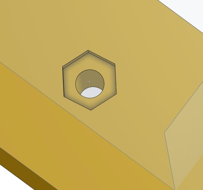
Is there a hole variant where the countersink is a hex or square nut. This is fairly common in 3D printer parts and laser cut panels where there is an inset of the nut to hold it from spinning while you screw from the other side. Yes, I realize I can make hexagons and rectangles and place them over the hole as a remove, but it would be way nicer if I could say (countersink-nut-trap-square) as a type of hole for M3, M5. etc... That way if the spec changes (was M3 now M5) everything could easily react. For example:
1
Best Answer
-
 coleman
OS Professional Posts: 244 ✭✭✭
There is no option for this feature currently. I suggest you submit a feature request....using the feedback button.
coleman
OS Professional Posts: 244 ✭✭✭
There is no option for this feature currently. I suggest you submit a feature request....using the feedback button.
The onshape team will notify you when and if your suggestion is implemented.5
Answers
The onshape team will notify you when and if your suggestion is implemented.
@henry_feldman
I really like this idea. If you don't mind I'll steal "adopt" it for my first attempt at a featurescript.
Cheers,
Owen S.
HWM-Water Ltd
Before I get further into it is this what you had in mind?
(1) Select Nut Type
(2) Select Thread
(3) Select point on sketch for nut pockets.
(4) Select Part to cut into.
(5) Decide if you wish the nut to be flush or sub-flush, and if sub-flush then by how much.
(6) Press green tick. The feature then looks up appropriate dimensions for the nut specified and builds the feature(s).
Anything else it needs to do?
Perhaps a parameter for how tight or loose to make them to tune to 3d printer capabilities?
Cheers,
Owen S.
HWM-Water Ltd
(1) I'll certainly add the smaller sizes if that's useful to you.
(2) Great idea on the inserts. I'd like to add those too but might hold back for little while to learn a little more first. There are so many different types; push fit, self tapping, heat stake etc. that all need different "pockets" be it counter-bored, chamfered, pilot, interference.
Currently the feature has hard-coded values for the options. Once I've learned a little more and can link to an external lookup table we can throw as many components as we like at it.
(3) As we're going to the trouble of creating a fixture pocket then it might as well have the option to put the nut in too and the option for a mate connector as well perhaps?
Regards,
Owen S.
HWM-Water Ltd
Regards,
Owen S
HWM-Water Ltd
Sure, anyone who'd like to use it is more than welcome to.
The beta is now available here :- https://cad.onshape.com/documents/1f9c312c2a22b9c3e6d350d2/w/7ab9048aa3617d42e5d237f2/e/6b6a63443330063ffe9c9b25
Hopefully its use is pretty self explanatory, if not I've done a bad job!
Inputs:- As many sketch points as you care to select and a body to cut into. (Points must be on surface of body.)
Options:- Nut shape (Hex, Square or Nyloc), Thread Size (M2 - M12), Clearance hole for thread through part (yes/no) and Build Pseudo Nuts (yes/no), and finally an option to have the nut subflush to the surface (and if so by how much.)
Outputs - A set of Nut Pockets, and if requested nuts.
Notes:-
(a) This is just an early beta, written by a complete newbie to fs, it is open to improvement.
(b) As far as I'm aware M2 and M2.5 Nyloc nuts are not available in the real world. If this option is selected the feature will fail. New version will inhibit these choices. This was incorrect, feature now supports M2 and M2.5 Nyloc Dimensions.
(c) The Pseudo nuts generated for Nyloc nuts are currently just taller hex nuts. The overall dimensions are correct so the pocket will be formed as required but the nut will not visually appear as if it's a nyloc.
(d) The holes through the Pseudo nuts are the correct pilot drill size for the thread so if one really wanted to print the nut and then tap it then it's possible.
Any problems, observations, comments or questions please shout.
Regards,
Owen S.
HWM-Water Ltd
Current version is now V0.5
Owen S.
HWM-Water Ltd
Just wondering if anyone has trialed the feature and if so what did you think of it?
Any feedback would be gratefully received.
Did it do what you wanted / expected?
Is there anything you think is missing that would be required to make it useful?
Thanks,
Owen S
HWM-Water Ltd
Awesome work buddy! Perfect Google, first hit result to this Forum article, used your link to incorporate into my sketch and voila! Works like a charm, does exactly what I wanted to do!
Huge thumbs up!
Thank you,
J
If OnShape was wondering if FeatureScript was worth it, this is a perfect example why it is awesome. And the power of these forums.
https://cad.onshape.com/documents/57af32cfe4b08c55288ef362/w/2a01fdd27e25062b9017a62a/e/652b83260c7b3bd5d5c77f20
HWM-Water Ltd
Damn! So sorry about that. I've tried to have a look at your doc but unfortunately it's shared as read only, please will you set it to allow a copy and I'll see what's going on?
Cheers,
Owen S.
HWM-Water Ltd
Thanks so much for this feature - got it to work, although I had the same error message as Mr. Feldman initially. Don't recall why. Just 3D printed the test part - looks good. Test part link:
https://cad.onshape.com/documents/ce25aae53984e57938274ccd/w/14a3c5a26abfe8df34a66c15/e/677c435fb648dc6f29deab83
If you're inclined to add to this, having an edge pocket in addition to the face pocket would be very useful.
Best regards,
- Al
The problem is slightly embarrassing. (Sorry again for wasting your time.)
The feature as it stands thinks it should build things "down", that is to say "through" the top of the sketch with the target points on it.
However in your example the your Extrude 1 is "up" out of your Sketch 1, not down below it. My widget then tries to make things in fresh air rather than in the Part 1. (If you turn off the through hole option (which is throwing the error) and instead check the add nut option you'll see it complete, but with the nut outside the part.)
I'll fix that properly before the V1 release but for today here are 2 workarounds:-
(1) Flip the extrude direction toggle in your Extrude 1. (In a real project this may be undesirable but will work fine in this scenario.)
(2) The better option. After the extrude feature create a new sketch on the face of Part 1 to put your points on. The "down" direction of any sketch will then be interpreted as towards the part.
Hope that helps to get the beta working for you. If you have any trouble then please don't hesitate to shout.
Thanks, Owen S.
HWM-Water Ltd
Quick question, maybe I am missing something and there is a way in Onshape itself to do this, but if you place let's say a hex nut, it is always orientated the same way.
In the below example, how would I go about rotating the nut 90deg clockwise?
Thanks,
J
Great question @jannie_van_der_walt and thanks @mahir for jumping in with a workaround. (Sorry I'm in the wrong time-zone...)
I've added an option to carry out this rotation:-
The two blue nuts are the original default orientation, and the new 3rd red nut is with the "Rotate (Point to flat)" option checked.
Hopefully that is what you had in mind?
Please note this option is no use whatsoever on the square nut as it's just a 90 deg rotation!
For anyone who already has "NP" installed then please update it (with a RMB on the "NP" feature icon and hit "update") or for anyone new wanting to use the feature then the current V0.6 beta is available here:-
https://cad.onshape.com/documents/1f9c312c2a22b9c3e6d350d2/w/7ab9048aa3617d42e5d237f2/e/6b6a63443330063ffe9c9b25
Cheers,
Owen S
HWM-Water Ltd
Also thanks for showing me the workaround @mahir will definitely come in handy in some other situations.
i am still learning this software, but as i see those small things/addons, i keep buying it more and more! TY
Thanks for the kind words and sorry I missed your post.
The nut pockets are automatically set to the thickness of the nut. You can make them deeper with the "sub-flush" option if you wish, but there is not an option to set them to an explicit depth.
You can also make use of the "move face" option (regular Onshape Icon, not part of the featurescript) to move the pocket face up or down if that helps.
Cheers,
Owen S.
HWM-Water Ltd