Welcome to the Onshape forum! Ask questions and join in the discussions about everything Onshape.
First time visiting? Here are some places to start:- Looking for a certain topic? Check out the categories filter or use Search (upper right).
- Need support? Ask a question to our Community Support category.
- Please submit support tickets for bugs but you can request improvements in the Product Feedback category.
- Be respectful, on topic and if you see a problem, Flag it.
If you would like to contact our Community Manager personally, feel free to send a private message or an email.
Knurled pattern on a flat surface
 graham_mills
Member Posts: 3 ✭
Hi,
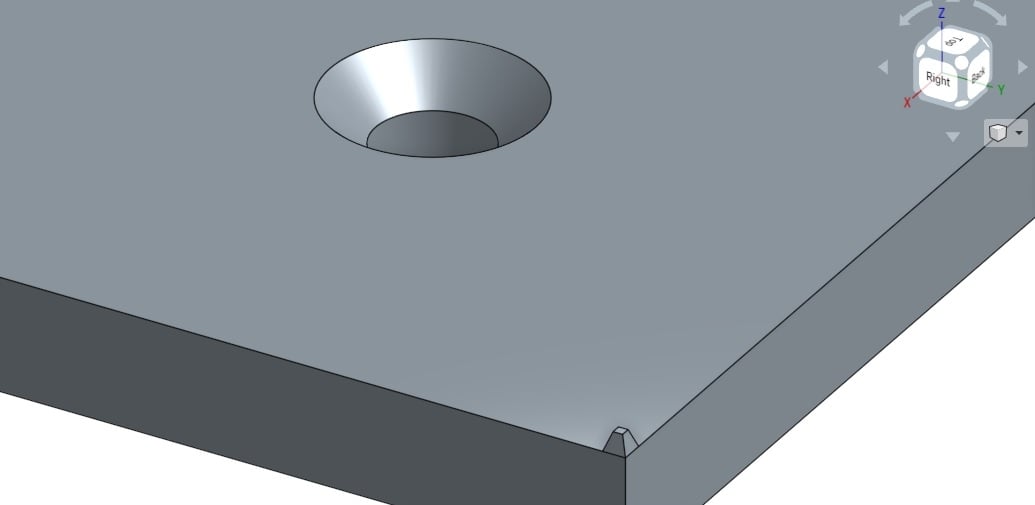
I'm trying to create a knurled pattern on a flat surface. It's a 5mm thick sheet of aluminium with grooves machined in the top (on the x and y axis), creating a pattern of little flat-top pyramids. This will be to provide grip on the finished product.
So far I've tried: making 2D pyramid pattern on the sides and extruding (with Remove) across the surface. This works in one direction but when I try to make the same pattern perpendicular to it the sketch fails as it's interfering with the first extrusion. I tried creating new planes on which to create the pattern and then extruding (Remove, Through all) across, but same again. I even tried making a simple pattern of one groove, extruding it into a V-cut, then using Linear Pattern to copy the groove across the rest of the surface. Problem with that is that as soon as I select the groove as an entity to use in a Linear pattern, the word 'Direction' appears in red and won't let me tell it which direction I want the pattern in...
The final thing I tried was this: creating one single small pyramid, then spreading it across the surface using a Linear pattern... same problem again with Direction showing up red with no options.

I found even just creating this little pyramid difficult. I'm still at the stage where I'm struggling with things that more experienced users wouldn't even need to think about.
Any idea how I can make this knurled pattern on the surface?
Cheers.
I'm trying to create a knurled pattern on a flat surface. It's a 5mm thick sheet of aluminium with grooves machined in the top (on the x and y axis), creating a pattern of little flat-top pyramids. This will be to provide grip on the finished product.
So far I've tried: making 2D pyramid pattern on the sides and extruding (with Remove) across the surface. This works in one direction but when I try to make the same pattern perpendicular to it the sketch fails as it's interfering with the first extrusion. I tried creating new planes on which to create the pattern and then extruding (Remove, Through all) across, but same again. I even tried making a simple pattern of one groove, extruding it into a V-cut, then using Linear Pattern to copy the groove across the rest of the surface. Problem with that is that as soon as I select the groove as an entity to use in a Linear pattern, the word 'Direction' appears in red and won't let me tell it which direction I want the pattern in...
The final thing I tried was this: creating one single small pyramid, then spreading it across the surface using a Linear pattern... same problem again with Direction showing up red with no options.

I found even just creating this little pyramid difficult. I'm still at the stage where I'm struggling with things that more experienced users wouldn't even need to think about.
Any idea how I can make this knurled pattern on the surface?
Cheers.
Tagged:
0
Best Answers
-
 brian_jordan
Member, Developers Posts: 144 ✭✭✭
Quick and dirty and not to scale but a linear patern of "V"s along the front and side faces followed by extrude remove seems to do it.
https://cad.onshape.com/documents/76895f360aefec55fd25a895/w/8631a28f306a2b27b5899824/e/c9c44ffd264893e054519a0b
5 -
 emagdalenaC2i
Member, Developers, Channel partner Posts: 863 ✭✭✭✭✭
Here is another option
https://cad.onshape.com/documents/adb788848a7ebf78a79f03b5/w/dc21daf2c68b97ebebeea49c/e/cba74d6d1099bd1ac24a7ab3
Un saludo,
Eduardo Magdalena C2i Change 2 improve ☑ ¿Por qué no organizamos una reunión online?
Partner de PTC - Onshape Averigua a quién conocemos en común2
Answers
https://cad.onshape.com/documents/76895f360aefec55fd25a895/w/8631a28f306a2b27b5899824/e/c9c44ffd264893e054519a0b
OK, I'll give it a go and let you know how I get on! Thanks for the reply, much appreciated.
Eduardo Magdalena C2i Change 2 improve ☑ ¿Por qué no organizamos una reunión online?
Partner de PTC - Onshape Averigua a quién conocemos en común
https://cad.onshape.com/documents/adb788848a7ebf78a79f03b5/w/dc21daf2c68b97ebebeea49c/e/cba74d6d1099bd1ac24a7ab3
Eduardo Magdalena C2i Change 2 improve ☑ ¿Por qué no organizamos una reunión online?
Partner de PTC - Onshape Averigua a quién conocemos en común
This kind of activity is extremely 'expensive' (slow) to rebuild and at scale represents significant increase in complexity to the total edge count.
If you HAVE to do this (because for instance you are going to 3D print this), please either suppress the features immediately after exporting the STL or even better, have the fully featured part on another branch.
Think about this - a complex casting might have 200 edges - just the simple example above has 1216 !!!
I realize that edge count is only a proxy for geometry complexity, but you get the idea.
Good luck!
Philip - that's a very good point. My computer is *really* slow anyway but I noticed it almost ground to a halt when I put the patterned surface on the shape it was originally designed for. My reason for doing it is that eventually I'd like to have the pieces CNC cut in aluminium and the machining will need to be done to the faces (they're car pedal covers; the brake and clutch need some 'grip'). Whether I could leave this off the finished CAD model and have the patterned machined another way might be a better way of doing it.
Cheers all.
Re 'your computer' - The only hardware dependent performance metric is shading speed.
If you go to cad.onshape.com/check, you will get a sense of how fast your graphics card is.
(<10 million triangles per second = slow. Fastest machines are around 350 million triangles per second)
The factors contributing to open time are;
- Time to process on our end (rebuild model and facetize)
- Time to pass new/different triangles
- Time for your machine to render them
The factors contributing to interactive performance (no re-calculation of sketches or geometry)- Ping time
Have fun.