Welcome to the Onshape forum! Ask questions and join in the discussions about everything Onshape.
First time visiting? Here are some places to start:- Looking for a certain topic? Check out the categories filter or use Search (upper right).
- Need support? Ask a question to our Community Support category.
- Please submit support tickets for bugs but you can request improvements in the Product Feedback category.
- Be respectful, on topic and if you see a problem, Flag it.
If you would like to contact our Community Manager personally, feel free to send a private message or an email.
How to create a Natural Spline / Minimal-Energy Spline
 sebastian_glanzner
Member, Developers Posts: 473 PRO
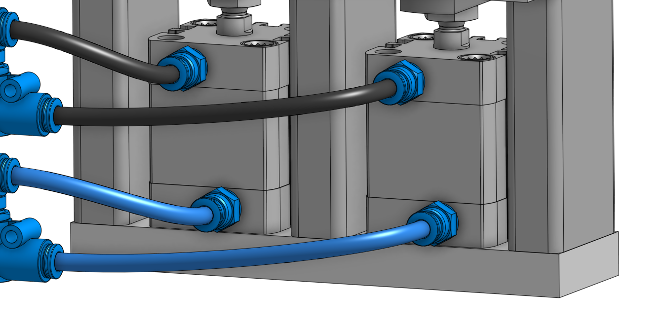
I'm working on a new FeatureScript to quickly create hose routings:

In the FeatureScript I can select a start, end and midpoints. A fitspline is going through all points.

Thanks

In the FeatureScript I can select a start, end and midpoints. A fitspline is going through all points.
- Now I would like to know how to create a "Natural Spline / Minimal-Energy Spline" This means that the spline should behave like a bend hose/wire.
- Can I define a minimal bend radius? This is necessary for pneumatic hoses.
- Is there a way to type in the length of the spline and fix that value?
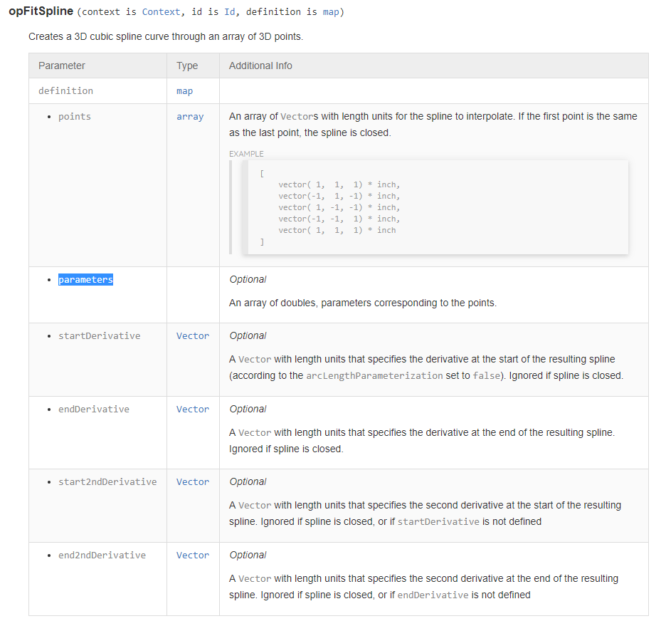
- Does anyone know what the parameters in the fitspline command do and how they are used?

Thanks
Tagged:
0
Comments
The documentation there seems to be saying that you can specify an explicit parameterization for each point of the spline.
An example:
- points = [A, B, C]
- parameters = [0, .9, 1]
A spline will be created passing through A, B, and C. 90% of the length of the spline will be between A and B. 10% will be between B and C.I'm turning your actual question over in my head but I don't have a great answer yet. I'll ask around.
The answer to the original question is that the requirements you describe (minimum bending energy, at least given bend radius, fixed length) all require nonlinear optimization -- there is no easy answer.
For shapes such as what you're looking for, I'd start by not having any intermediate points and just optimizing over start and end derivatives. You won't get great answers, but you'll get simple curves that work reasonably. If you actually do try more complete optimization (which I would not recommend if your goal is to do something relatively quickly), opCreateBSplineCurve will probably be better, as at least the derivative matrix of positions as a function of control points is sparse.
Thanks for the explanation of the parameters!
@ilya_baran
Thanks for your suggestions! I'm now using splines with two points and startDerivative and endDerivative, it looks quite good!
I create 4 splines for each segment (one for each combination of normal-directions) and select only the shortest spline for the sweep.
This way the user does not have to select the correct directions
If you want to avoid doing four geometric operations and then deleting 3 of them, consider the following algorithm for each side:
Thank you very much! This was exactly what I needed!
I will release a public version as soon as I cleaned up the code and tested it.
Owen S.
HWM-Water Ltd
If a spline starts and ends in the same plane I get an "S" Shaped spline as result.
So I tried to create two alternative spline with the end normal switched:
Now I have get Onshape to select the correct spline automatically. Unfortunately I can't select the shortest spline, because that would be the "S".
But the Curvature shows which is the "better" spline:
So I used evEdgeCurvatures() to get the curvature along the spline at multiple points. Then I search for the max curvature, compare it with the max curvature of the other spline and select the curve with the lowest value.
But I have to do this for at least 20 points along the curve and this cost a lot of time.
        var parameterCurvature = [];
        var indexCurvature = [];

        for (var i = 0; i < 21; i += 1)
        {
            parameterCurvature = append(parameterCurvature, roundToPrecision(1 / 20 * i, 2));
            indexCurvature = append(indexCurvature, i);
        }

        var curvatureAlternativeA = 0;
        var curvatureMaxAlternativeA = 0;

        var currentCurvature;

        curvatureAlternativeA = evEdgeCurvatures(context, {
            "edge" : qCreatedBy(id + ("splineA" ~ i), EntityType.EDGE),
            "arcLengthParameterization" : true,
            "parameters" : parameterCurvature
        });

        for (var i = 0; i < size(indexCurvature); i += 1)
        {
            currentCurvature = abs(curvatureAlternativeA[i].curvature * meter);
            if (currentCurvature > curvatureMaxAlternativeA)
            {
                 curvatureMaxAlternativeA = currentCurvature;
            }
        }
Does anyone know how I can get the max curvature of a spline without this iteration?
IR for AS/NZS 1100
I will have to try that, thanks
I could also check if the next point is exactly in the normal direction of the first point.
If true, this segment can be a line instead of a spline
IR for AS/NZS 1100
One of the tricks we use internally is that we would make a feature like this take only sketch points, and then use the normal of `evOwnerSketchPlane` as the normal of each point. Flips could be applied to this if necessary, but in the ambiguous case, just trust the user's sketch plane (and they can select a different plane if its wrong)
HWM-Water Ltd
Circular face does not define a center point, just a center axis.
Circular edge is nice because it probably has a circular or cone face coming off one side of the edge, and a plane or similar coming off the other side of the edge (assuming the body is solid, which implies there are two faces attached to the edge). In a case like that it seems (from the given examples) that the edge wants to go away from the circular face.
Another thing that could be done is that the selection could be an array parameter, each of whose inputs has a selection and a direction flip, which would override the original heuristic that is being applied.
HWM-Water Ltd
A long term solution might be that your company could own their own branch of this FS, which incorporates an additional small piece of code to mark that property as desired. But as it currently stands you would need to copy the FS, and incorporate it, which maintains no associativity to the original FS. Internally we are always thinking about stuff like being able to keep your own "fork" of a FeatureScript and pull updates from the master while keeping your own company changes private, but I think the solutions others have been using right now is to create a repository on GitHub for the feature, and maintain a fork there. The project to improve these kinds of workflows is more on the horizon than knocking on the door.
HWM-Water Ltd
HWM-Water Ltd
I think the regen would be fine, but it seems like it's making a company-specific change to a geometric feature that is otherwise completely general.
Also, it would expose the internal ids of your company to the public eye, which isn't the worst thing in the world but probably not ideal?
I do think that your idea would work functionally, and feel free to move forward with it if Sebastian agrees, but I don't think it's a great design decision.
I think a better design from the FS designer point of view would be to introduce a "keep curve" option which would keep the original curve around in the curve list on the left. Then it would be super easy to write an additional FeatureScript which takes the curve, measures its length, and sets whatever properties you want on another selected body (it could even then take charge and delete those curves if you want).
In FS curves are called "wire bodies". I have called them curves above ^ because it is very ambiguous what I mean when I say "wire body" in a thread about making solid bodies to represent wiring
IR for AS/NZS 1100
https://forum.onshape.com/discussion/11110/new-featurescript-hose-routing/
Thanks everyone!