Welcome to the Onshape forum! Ask questions and join in the discussions about everything Onshape.
First time visiting? Here are some places to start:- Looking for a certain topic? Check out the categories filter or use Search (upper right).
- Need support? Ask a question to our Community Support category.
- Please submit support tickets for bugs but you can request improvements in the Product Feedback category.
- Be respectful, on topic and if you see a problem, Flag it.
If you would like to contact our Community Manager personally, feel free to send a private message or an email.
Options
Secondary Datum Information on Geometric tolerances.
Hi,
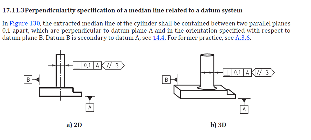
I need to specify a perpendicular tolerance to a datum A with a known tolerance value. However the extracted median plane is also perpendicular to another datum plane B but it is just a specification of orientation wrt datum B. How can I provide this secondary information in Onshape drawing?
The nearest example I can show here (which is very similar to my case) is explained in ISO1101 document as attached in the photo. In the photo example, the extracted plane orientation is parallel to B.

0

Comments
Question - how is that secondary datum used? Does this go along with another tolerance? I just do not see what the B datum frame adds.
And to answer your question, think about the example I presented in my question, i.e. figure 130 from ISO1101 document. Suppose, I only give the tolerance of perpedicularity of 0.1 wrt A, it will leave an ambiguity as shown in the photo (top view):
The extracted median line of cylinder (point in the top view) is contained between two parallel planes (lines in top with view) 0.1mm apart which are perpendicular to datum A. In both case-A and case-B, this statement holds true. And, it leaves an ambiguity and is not very precise.
However, if I require very precise and less ambiguous tolerance notation, lets say I need to avoid instances like case-B, I will specify orientation of planes wrt secondary datum. In the end, it all comes down to designer choice on how much information he/she wants to communicate in drawings depending on functionality of the part. In most cases, it might not be necessary but in some cases its absolutely necessary.
In the past, I used to utilise two tolerances to achieve the same Case-A. I have came across this new method recently and its been published in 2017, which is not very long ago.
glad the work around will let you get by!
I appreciate your explanation of the example - I see your intent of making a perpendicular parallel 0.1 zone which needs to be defined in rotation to 2nd datum.
However, I thought perpendicularity is a cylindrical tolerance zone; so your CASE-A would show a 0.1 circle as top of cylindrical tolerance zone. Does perpendicular change to parallel planes zone when you add the second datum frame? Or is there a more general tolerance we have not seen which is further refined by this double frame?
edit - I should break down and get a book! thanks again for your explanation...
Perpendicularity or parallel tolerances are controlled zones between two parallel planes, thats why secondary datum is necessary in some cases. If we don't provide this secondary tolerance, there is no difference between case-A and case-B, and I can say tolerance zone looks like a circle (in top view), i.e. cylindrical tolerance zone as you explained.
No, the perpendicularity still remains the same. You can read the description(17.11.3) in the photo I have attached in question. The tolerance zone is still perpendicular to datum A and should remain so. The secondary information provides orientation of these planes.
In the past, I have tried to find some books related to design and geometric tolerances, but none have given me perfect explainations. And this lack of knowledge affected my designs sometimes. So, for last 1 year, I started refering to documents or standards published by ISO. And in them you can find everything you require, with examples, ambiguous and non-ambiguous representation of same dimensions with different tolerance parameters, etc.
Some ISO standards I refer commonly to get this information are as follows:
ISO 1101: GPS - Geometrical Tolerancing - Tolerances of form, orientation, location and run-out.
ISO 5459: GPS - Datums and datum-systems
ISO 14405: GPS - Dimensional Tolerancing (has three parts)
ISO 17450: GPS - General concepts (has four parts)
thanks for that detailed explanation and references. I feel the same way about not finding the study aids and really appreciate the references you gave. I will read up!