Welcome to the Onshape forum! Ask questions and join in the discussions about everything Onshape.
First time visiting? Here are some places to start:- Looking for a certain topic? Check out the categories filter or use Search (upper right).
- Need support? Ask a question to our Community Support category.
- Please submit support tickets for bugs but you can request improvements in the Product Feedback category.
- Be respectful, on topic and if you see a problem, Flag it.
If you would like to contact our Community Manager personally, feel free to send a private message or an email.
Voids of unknown origin
 tom_seibold
Member Posts: 20 ✭✭
tom_seibold
Member Posts: 20 ✭✭
Considering what a friendly welcome I was given the first time I posed a question about modeling a part, I thought I'd throw out another challenge to the skilled and helpful individuals who monitor this community.
I completed my model (which those who helped may with my extruded logo path may remember), which is part that goes into a Bluetooth speaker housing and holds a power switch and some small circuit boards. I exported it to STL, examined the file in two different STL viewers, and saw no problems. Then I uploaded it to Shapeways for printing.
Unfortunately, when I got the model back, there was a strange void that sliced across the tubular flange and crossed into two of the holes on the mounting flange. I hadn't seen such voids in my STL viewer, but when I looked at the file I'd uploaded in SW's online viewer, there it was. (Text continues below images.)
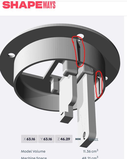
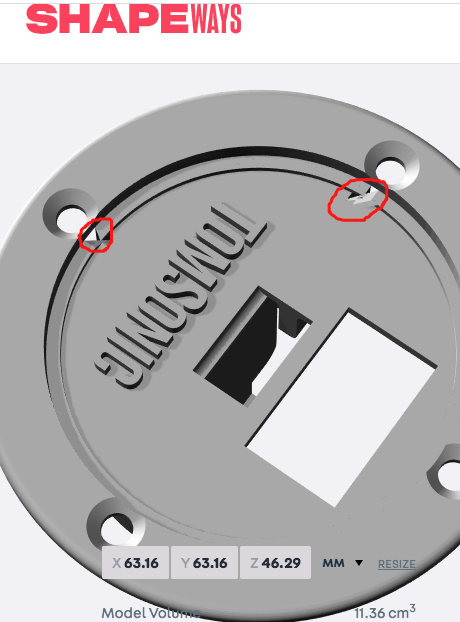

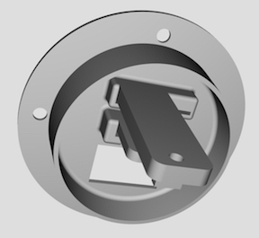
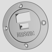
I contacted Shapeways, and their tech support said "This looks like there was an issue with the geometry, some faces may have been inverted. When you uploaded your model, our system tried to automatically fix these issues, which unfortunately caused the holes." The seemingly random angle of this void doesn't help me with troubleshooting, and I'm not sure how faces got inverted, if that's actually the cause. All I know is that the part looks fine in both my STL viewers, as shown below. (Text continues below images.)
If you'd like to examine my model and see if you can track down the problem, here's a link generated by the "Share" function (which appears to be the same as the actual URL). Note that I am working in the "Rev Dim 1" branch/workspace.
https://cad.onshape.com/documents/699a9674479007024e599743/w/d970435e2789ad48186baaba/e/4fb5d462993aa511cef60aee
I completed my model (which those who helped may with my extruded logo path may remember), which is part that goes into a Bluetooth speaker housing and holds a power switch and some small circuit boards. I exported it to STL, examined the file in two different STL viewers, and saw no problems. Then I uploaded it to Shapeways for printing.
Unfortunately, when I got the model back, there was a strange void that sliced across the tubular flange and crossed into two of the holes on the mounting flange. I hadn't seen such voids in my STL viewer, but when I looked at the file I'd uploaded in SW's online viewer, there it was. (Text continues below images.)
I contacted Shapeways, and their tech support said "This looks like there was an issue with the geometry, some faces may have been inverted. When you uploaded your model, our system tried to automatically fix these issues, which unfortunately caused the holes." The seemingly random angle of this void doesn't help me with troubleshooting, and I'm not sure how faces got inverted, if that's actually the cause. All I know is that the part looks fine in both my STL viewers, as shown below. (Text continues below images.)
If you'd like to examine my model and see if you can track down the problem, here's a link generated by the "Share" function (which appears to be the same as the actual URL). Note that I am working in the "Rev Dim 1" branch/workspace.
https://cad.onshape.com/documents/699a9674479007024e599743/w/d970435e2789ad48186baaba/e/4fb5d462993aa511cef60aee
Tagged:
0
Answers
Does it look ok in other third part viewers? For example: https://www.viewstl.com/
If it looks ok in Onshape, and it looks ok in your STL viewer, and looks ok on that site, it seems like Shapeways probably has a bug in their import.
So I think this issue might be based on how I constructed the model. In this section view, it's clear that the things I added "below" the main plate are "merged" into the model, as if in one piece. But in the area "above" the main plate, the mounting flange actually is just edge to edge with the tubular ring below it, and there's only the filleted rounded ring (not visible on the yellow-line analysis above) that joins the two together--And, at that, they don't appear to be joined, just adjacent, based on those black lines I'm seeing. Time to do some model dissection and see if I can do better . . .
You can either select all of the parts and do a "boolean" operation to add them together. Or, you can go through the operations the created the parts (such as extrude and revolve) and make those operations are set to "add" to any existing parts. Check out the help page for the Extrude function and look for the heading "Extrude: New/Add (new material)": https://cad.onshape.com/help/Content/extrude.htm?tocpath=Part%20Studios%7CFeature%20Tools%7C_____1
HWM-Water Ltd
@owen_sparks - You're right--I'm not even sure how I got three different colors, but it appears to be just a setting under "Edit appearance."
When you create more than one part, Onshape automatically assigns different colors to each part so that its easier to tell them apart.