Welcome to the Onshape forum! Ask questions and join in the discussions about everything Onshape.
First time visiting? Here are some places to start:- Looking for a certain topic? Check out the categories filter or use Search (upper right).
- Need support? Ask a question to our Community Support category.
- Please submit support tickets for bugs but you can request improvements in the Product Feedback category.
- Be respectful, on topic and if you see a problem, Flag it.
If you would like to contact our Community Manager personally, feel free to send a private message or an email.
Options
Small scale flat surface not flat?
 Vītols
Member Posts: 4 ✭✭
This spline sided swept surfaces' flat(!) top is divided by a line in order to "Move face (rotate)" to make a kind of a ramp.
Problem: I can select part of the surface, but not when in move face function.
Line is 1mm long for scale


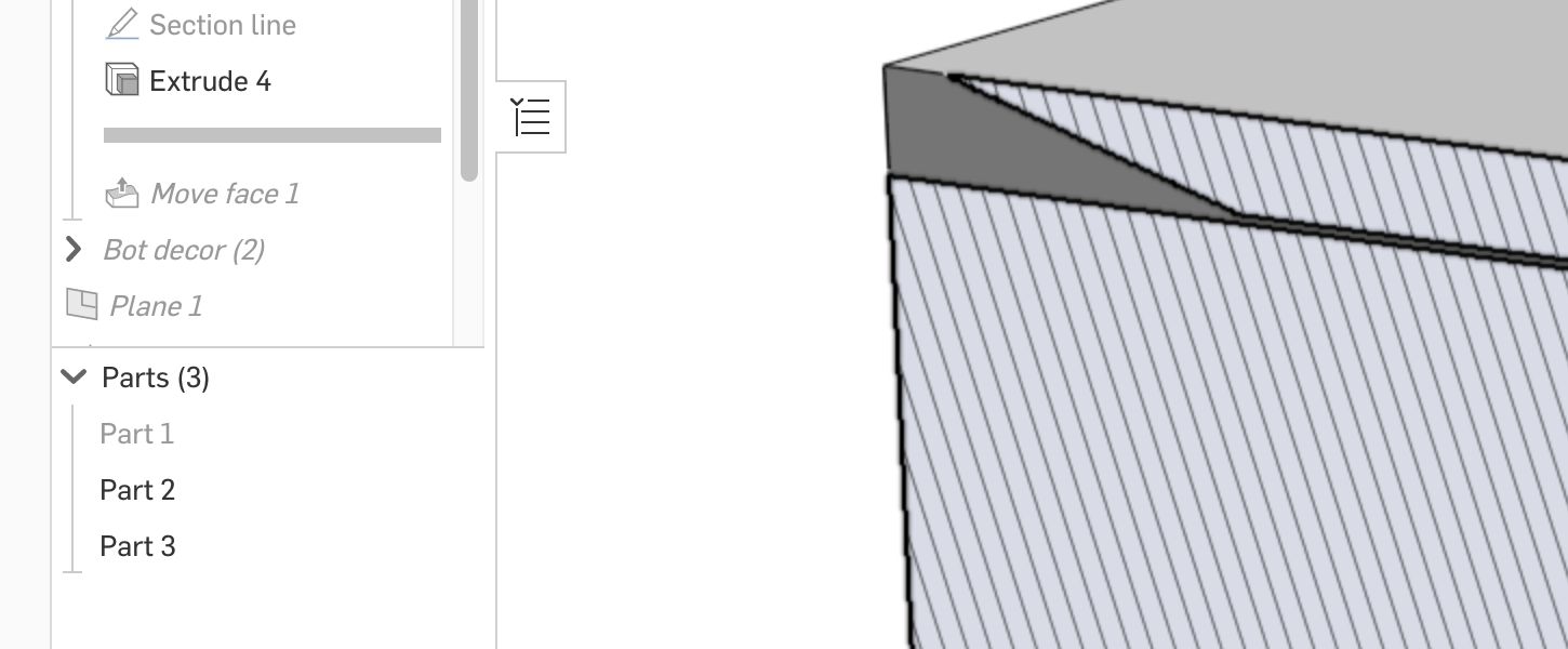
Then I make small "extrude (remove)" 0.01mm after this I can rotate that part of surface (as aworkaround), but extrude reveals a diamond shape not a rectangle as expected. Diamond shape appears after extrude
Tessellation quality set to very fine.
After 0.02mm extrude, I can see something:
Note that section view in theory is parallel to that small narrow rectangle


So I guess this is because of sweep takes the rectangle profile and kind of rotates it along the path making these micro prisms or something?, but still, result should be the same no matter if part is extruded or swept (Yes/no?).
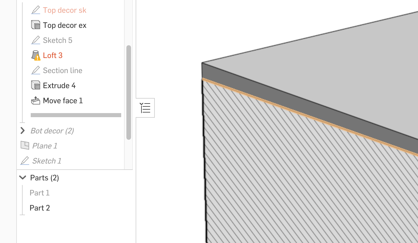
Extruded part works better: Smallest extrude I could do was 0.002mm. Could not rotate surface without this workaround.
Section view works as expected.

Any comments appreciated on this sweep quality thing and also, why not possible to divide surface with a line (or perimeter lines) and rotate only that part of surface ?
Problem: I can select part of the surface, but not when in move face function.
Line is 1mm long for scale

Then I make small "extrude (remove)" 0.01mm after this I can rotate that part of surface (as aworkaround), but extrude reveals a diamond shape not a rectangle as expected. Diamond shape appears after extrude

Tessellation quality set to very fine.
After 0.02mm extrude, I can see something:
Note that section view in theory is parallel to that small narrow rectangle

So I guess this is because of sweep takes the rectangle profile and kind of rotates it along the path making these micro prisms or something?, but still, result should be the same no matter if part is extruded or swept (Yes/no?).
Extruded part works better: Smallest extrude I could do was 0.002mm. Could not rotate surface without this workaround.
Section view works as expected.

Any comments appreciated on this sweep quality thing and also, why not possible to divide surface with a line (or perimeter lines) and rotate only that part of surface ?
0
Best Answer
-
Options
 S1mon
Member Posts: 2,365 PRO
If you could share a public document, it might be easier to help. Also ultimately, what are you trying to represent with the feature(s)? There may be another way to solve the problem.
This may be obvious, but there are a couple things going on:- What you see on screen is by definition an approximation of your model. Everything gets turned into triangles to render the view you see, and the tessellation quality can affect what you see. You can change from tessellation from auto to fine or very fine (context menu on part: Edit Appearance).
- Very small features (relative to the overall size of the part studio) are harder for the system to resolve. The math of all NURBS based CAD systems (almost all mechanical CAD) is such that there is no convenient closed-form solution for the general intersection of surfaces. It's always done as an approximation (not the same problem at #1). How small the error band is around each surface intersection drives some of the rebuild time, and it also drives whether features work or not. This is also a big source of issues when importing/exporting from one CAD system to another. Each system handles this accuracy issue differently. Even though the fundamental math behind NURBS is the same in all these systems, the implementation of the intersections is not the same.
- It sounds like you're already trying this, but trying out different values other than your design intent can sometimes help find the source of the problem.
1
Answers
This may be obvious, but there are a couple things going on: