Welcome to the Onshape forum! Ask questions and join in the discussions about everything Onshape.
First time visiting? Here are some places to start:- Looking for a certain topic? Check out the categories filter or use Search (upper right).
- Need support? Ask a question to our Community Support category.
- Please submit support tickets for bugs but you can request improvements in the Product Feedback category.
- Be respectful, on topic and if you see a problem, Flag it.
If you would like to contact our Community Manager personally, feel free to send a private message or an email.
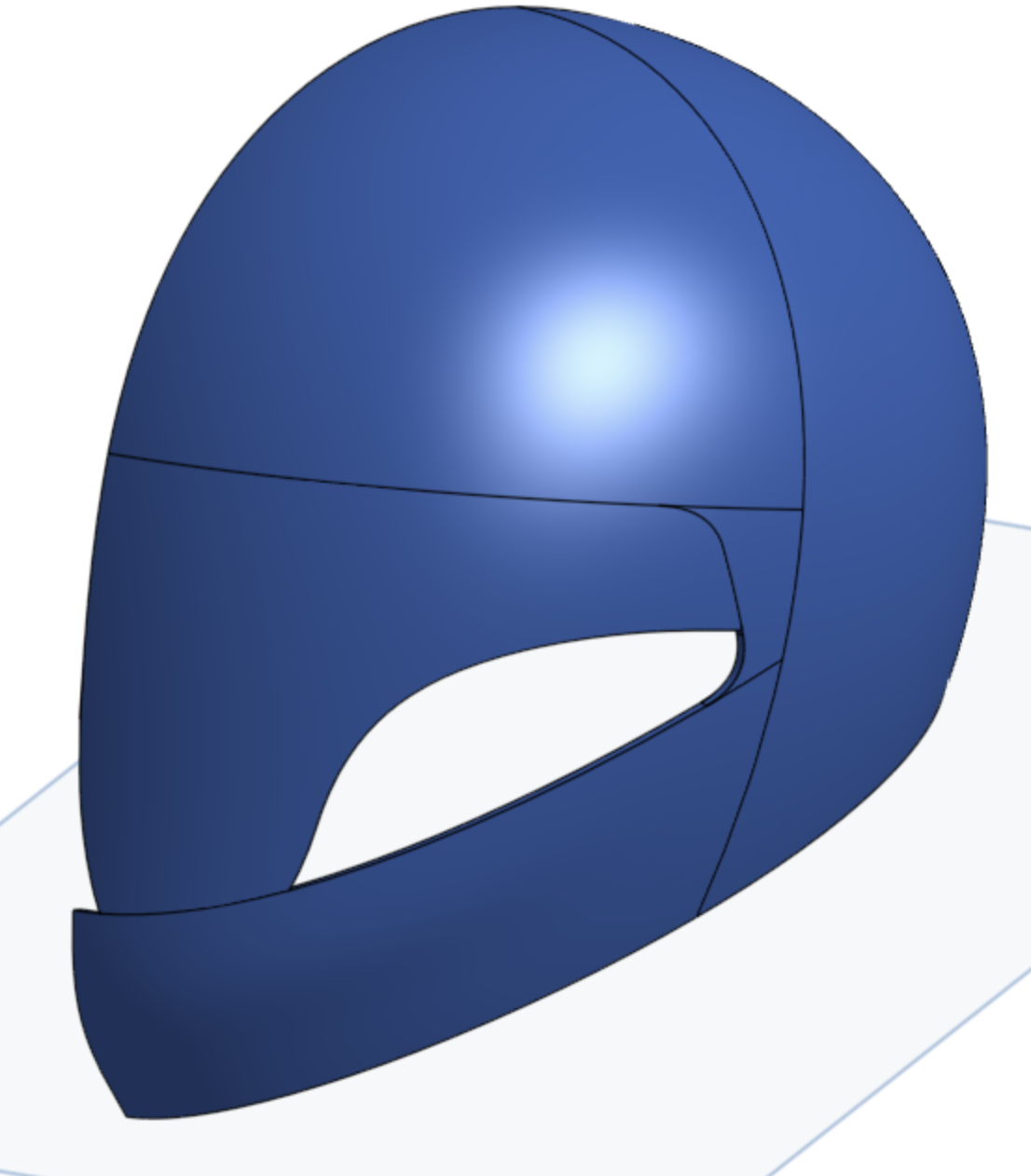
Shell is doing something strange

Best Answer
-
Hi Martien,I replied to your support ticket, but I thought I'd share with the rest of the group as well.
The issue on this one is that the 80 dimension for the spline handle should be a vertical dimension instead of an angled 80.
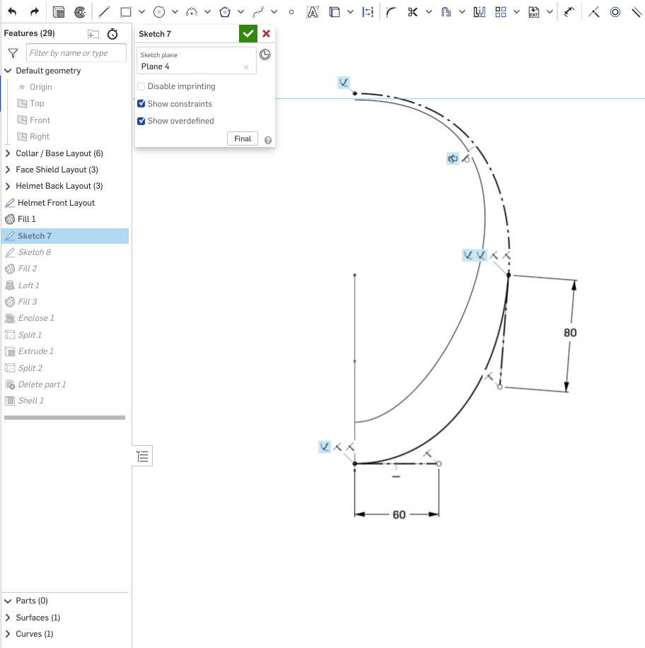
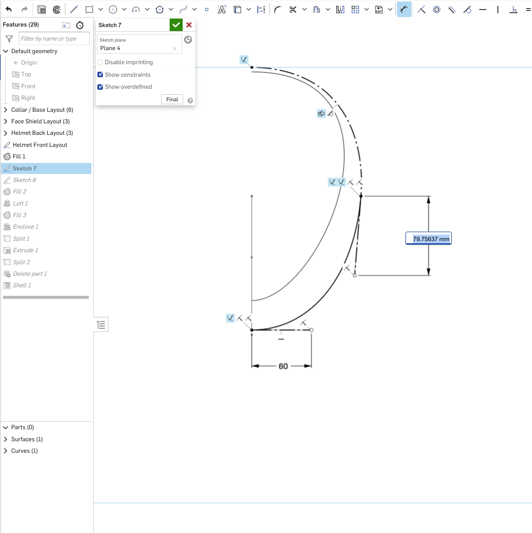
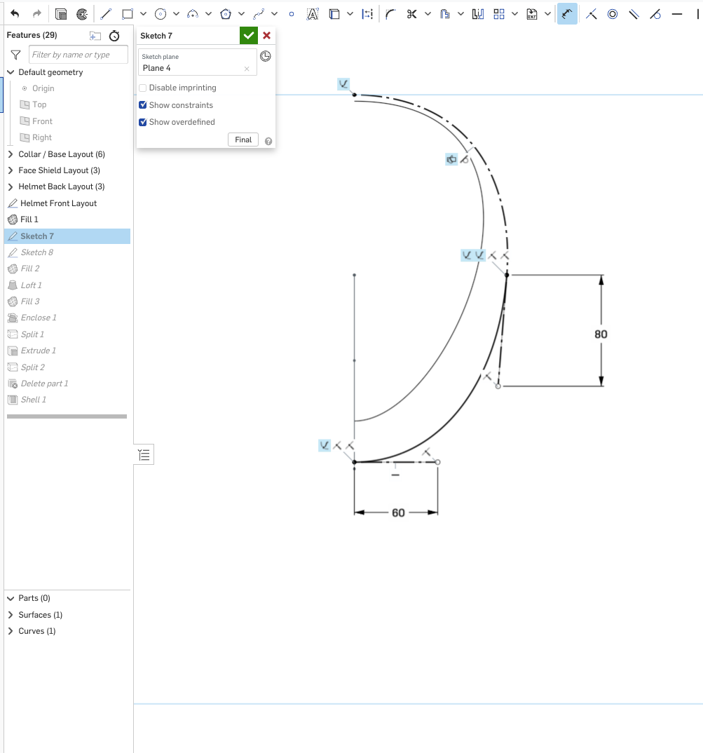
Correcting that dimension seems to bring the rest of the part studio back as expected. This detail is added as a "Hint" in the instructions for Step 3, but it is sometimes missed because you have to scroll down on the slide.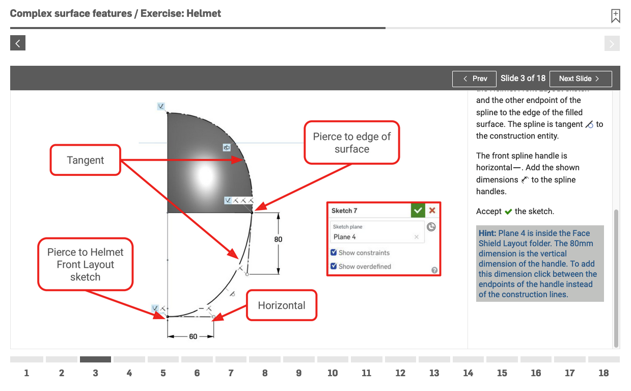
1


Answers
-
I've used Onshape for ~7 years and CAD like it for much longer. You've found a very odd thing here and the solution isn't obvious to me. I'd imagine it has something to do with the underlying surfaces, which, of course, depend on the underlying curves that create them. That said, I don't have time to dig into it right now. Rather than troubleshoot this one, my suggestion would be to start the course from scratch and pay close attention to the steps. In doing so, hopefully you'll be able to see where you went wrong and I'd love if you'd report back about it.1
-
That does look pretty odd...
I would add that you should submit a ticket (use the "contact support" in the help menu), as this looks like a bug to me, or at least something the Devs should know about in case they don't see this thread!1 -
In this particular case, you could cut the visor opening across and then do the shell. The edges of the shell wouldn't be normal to the outside any more, but it does work. Here's a quick version of that:

https://cad.onshape.com/documents/7b8c28ecd38bf8d1cbb11761/v/8eac529d8b673afdfce64a2e/e/ec53fa0fa89b39372135a281
I was actually surprised to see that shell will take a face which is created by split, and generally do something intelligent. I created a really simplified version of the topology and it worked.
Simon Gatrall | Product Development, Engineering, Design, Onshape | Ex- IDEO, PCH, Unagi, Carbon | LinkedIn
1 -
@S1mon
If you cut the visor using a "thicken" it stays normal and works:
https://cad.onshape.com/documents/f0d893848fb30200bea4ba76/w/04c13c41f6832154cac95f25/e/35de0263b0c392d62b0d38a4
1 -
Ok, I redid the exercise up to the same point, see https://cad.onshape.com/documents/03a3955ea16e24c4d96cef07/w/f1dd8d63559b372315def399/e/d4601a4a0238a16a512b6ca1
This time, I do not have the same problem. I'll try to use my very limited knowledge to try to work out whether I can find any problem that might explain what is going on here. If anyone has suggestions what to look for, please,
0 -
As an update. I just went through the two documents side by side (after renaming the features back to their defaults, so everything would be the same). I went into each feature, and checked whether it was identical in both documents, to the point of making sure all selections were in the same order. No luck.As far as I can tell, the features in the timeline are identical, but I still end up with a different result. I'll see if I can work out again how to pull out the FeatureScript, and see if I can diff the two...0
-
Ok, I think I have gone as far as I can.I pulled the code/featurescript out of both of the above part studios. Saved them to local files, and used VS Code to compare them.All automatically generated identifiers are of course different, which makes checking references hard, but I already tried to do that in the previous step, so I assume that I can simply look at the "shape" of each block, and compare those.Initially found no meaningful differences, except maybe in sketch 8 where I had projected an extra line, and had some extra constraints. SO I branched and removed those extra sketch entities. However, this had no result. The original attempt at this tutorial is still broken.The two documents are now almost identical, I think, apart from the automatically generated identifiers, and the order of some of the operations or constraints in the sketches. And they still result in a different outcome.Either way, this is staring to look like there is something odd and buggy going on.To work out whether the problem would survive copying data, I also tried duplicating the tab (which results in two tabs with broken geometry) and moving the tab to a new document (which also results in the broken geometry). I saw the 'copy to clipboard' in the context menu for the part studio tab, but I don't know what to do with that copied tab, how to paste it.If someone has suggestions for other things to try, I'd like to hear.I'll leave this here for a week or so, and then maybe see if I should raise it as a possible bug.0
-
In looking at your first document, I did some experimentation and made a number of parts studios. So the text below is in reference to some of those parts studios I made
In another 3-D app that I have, which I haven’t actually used much in a long time, but if I remember that program correctly, it seems as though the direction of splines around a shape at time could possibly flip the normals to where the outward facing surfaces of parts or objects could actually flip to where the normal was facing towards the inside of the part. And would give an absolute black appearance when this happened. As such, they had a flip normals tool
Now I don’t know if any of that is coming into play here, but it may be a direction of splines thing ??
On some of the part studios, I did get aberrations, as if the above was almost something that could be happening
Now I got a 2.42 thickness to work.
But at a .05 shell, there are the aberrations. As if the inside face to outside face distance is not consistent in thickness at those aberrations, to where the backside of the interior face is actually poking through the outside face and vice versa, giving this inside-out of normals appearance
When the shell gets to .14, the aberrations go away
When you go over 2.42, things go bananas again.
1 -
I probably shoukd add here that the other program I talked about above, where the normals could get flipped, did use the ACIS geometric modeling kernel. So it’s VERY possible that what I said above has no relevance
0 -
Update: I contacted support, and they found the problem, or rather, they found out what _I_ did different that shows this problem.On sketch 7 there is an 80 mm dimension on a spline handle, that I put on the length of the handle, and it should have been vertical. The result is a 0.2 mm difference in the length of that handle, which causes this to happen. (There is a note in the exercise that tells people to pay attention to this, and I missed that. Every time I went through it, I missed it. That's on me.)I would still regard the oddity as a bug somewhere. It seems that I would expect some error in invalid geometry to prevent us from being able to end up on the shell's weird behaviour, but I'll leave that with the devs to work out1
-
Hi Martien,I replied to your support ticket, but I thought I'd share with the rest of the group as well.
The issue on this one is that the 80 dimension for the spline handle should be a vertical dimension instead of an angled 80.
Correcting that dimension seems to bring the rest of the part studio back as expected.This detail is added as a "Hint" in the instructions for Step 3, but it is sometimes missed because you have to scroll down on the slide.
1 -
Wow. Onshape’s incredible support team in action.Senior Director, Technical Services, EMEA0
-
I did the same mistake, but had a different symptom. The shell completely failed for me if I included the face shield face. I thought it was because in a change of how things worked since the exercise was created, so I just used the face shield surface with a thicken remove instead. It seemed to do the trick until I came to the mirroring where the boolean operation failed. Thanks to finding this thread I got it sorted. I'm not entirely sure what is happening though, shouldn't this difference only make a cosmetic difference in how the helmet appeared?0