Welcome to the Onshape forum! Ask questions and join in the discussions about everything Onshape.
First time visiting? Here are some places to start:- Looking for a certain topic? Check out the categories filter or use Search (upper right).
- Need support? Ask a question to our Community Support category.
- Please submit support tickets for bugs but you can request improvements in the Product Feedback category.
- Be respectful, on topic and if you see a problem, Flag it.
If you would like to contact our Community Manager personally, feel free to send a private message or an email.
Shell is doing something strange
 martien
Member Posts: 15 ✭✭
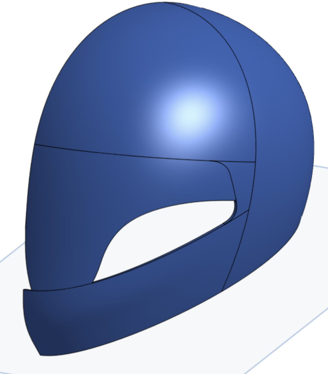
I am currently working through the surface modelling lessons/tutorials, and am working on the helmet model (part of https://learn.onshape.com/learn/course/onshape-surface-modeling/complex-surface-features/exercise-helmet). I think I've done everything right up to here, but when I try to shell the helmet part, as soon as I click the surface that is split out for the visor, I get a very strange result.

I would have expected the surface that I selected to be properly removed, but I seem to be getting some odd shaped piece appearing instead (and I do not even understand where that would be coming from.
Now, before assuming there's a bug somewhere, I assume that I have done something wrong somewhere, but I can't figure out what it is that would be causing this.
This is what I have done: https://cad.onshape.com/documents/5c4c9329812de0b5c7e61552/w/6f1b1477874aee8bb25f5d86/e/ffc0816f66506398ba0212ab
If anyone has any suggestions, that would be welcome.
Thanks
0
Best Answer
-
 jmoellers
Member Posts: 3 ✭
Hi Martien,I replied to your support ticket, but I thought I'd share with the rest of the group as well.
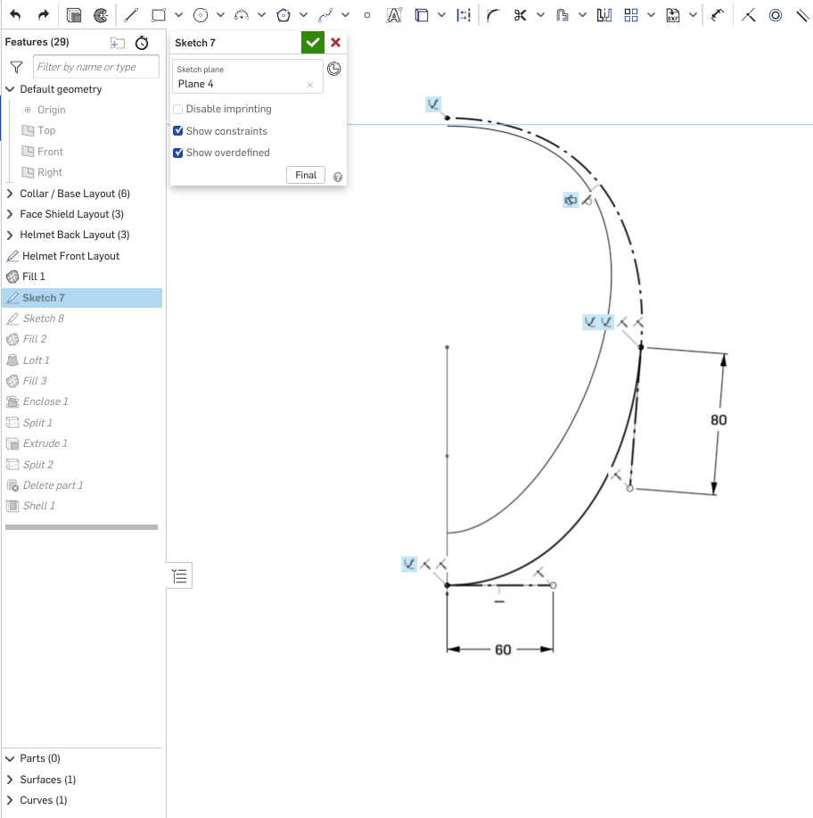
The issue on this one is that the 80 dimension for the spline handle should be a vertical dimension instead of an angled 80.


Correcting that dimension seems to bring the rest of the part studio back as expected. This detail is added as a "Hint" in the instructions for Step 3, but it is sometimes missed because you have to scroll down on the slide.
1
Answers
The Onsherpa | Reach peak Onshape productivity
www.theonsherpa.com
I would add that you should submit a ticket (use the "contact support" in the help menu), as this looks like a bug to me, or at least something the Devs should know about in case they don't see this thread!
https://cad.onshape.com/documents/7b8c28ecd38bf8d1cbb11761/v/8eac529d8b673afdfce64a2e/e/ec53fa0fa89b39372135a281
I was actually surprised to see that shell will take a face which is created by split, and generally do something intelligent. I created a really simplified version of the topology and it worked.
Simon Gatrall | Product Development, Engineering, Design, Onshape | Ex- IDEO, PCH, Unagi, Carbon | LinkedIn
If you cut the visor using a "thicken" it stays normal and works:
https://cad.onshape.com/documents/f0d893848fb30200bea4ba76/w/04c13c41f6832154cac95f25/e/35de0263b0c392d62b0d38a4
This time, I do not have the same problem. I'll try to use my very limited knowledge to try to work out whether I can find any problem that might explain what is going on here. If anyone has suggestions what to look for, please,
In looking at your first document, I did some experimentation and made a number of parts studios. So the text below is in reference to some of those parts studios I made
In another 3-D app that I have, which I haven’t actually used much in a long time, but if I remember that program correctly, it seems as though the direction of splines around a shape at time could possibly flip the normals to where the outward facing surfaces of parts or objects could actually flip to where the normal was facing towards the inside of the part. And would give an absolute black appearance when this happened. As such, they had a flip normals tool
Now I don’t know if any of that is coming into play here, but it may be a direction of splines thing ??
On some of the part studios, I did get aberrations, as if the above was almost something that could be happening
Now I got a 2.42 thickness to work.
But at a .05 shell, there are the aberrations. As if the inside face to outside face distance is not consistent in thickness at those aberrations, to where the backside of the interior face is actually poking through the outside face and vice versa, giving this inside-out of normals appearance
When the shell gets to .14, the aberrations go away
When you go over 2.42, things go bananas again.
https://cad.onshape.com/documents/5846fc56d4c72e4f98c46e28/w/47579ac64f4049c47604c500/e/373897c99ae1050b580b481e
The issue on this one is that the 80 dimension for the spline handle should be a vertical dimension instead of an angled 80.
Correcting that dimension seems to bring the rest of the part studio back as expected.