Welcome to the Onshape forum! Ask questions and join in the discussions about everything Onshape.
First time visiting? Here are some places to start:- Looking for a certain topic? Check out the categories filter or use Search (upper right).
- Need support? Ask a question to our Community Support category.
- Please submit support tickets for bugs but you can request improvements in the Product Feedback category.
- Be respectful, on topic and if you see a problem, Flag it.
If you would like to contact our Community Manager personally, feel free to send a private message or an email.
Designing my own desktop for a desk
 masta_killa
Member Posts: 12 ✭
masta_killa
Member Posts: 12 ✭
Intro
Hi everyone,
I'm still new to OnShape and I only have a bit of experience with SketchUp (which I also didn't use anymore for some time already).
I probably won't understand you if you try to explain things with words, so if possible please show me with a short video or any other way you think might be more understandable.
I did already try finding a solution by searching on Youtube, but I couldn't find anything applicable or understandable for me (but probably I simply didn't use the correct search terms).
Thanks a lot for your understanding and support!
So I'm trying to design my own, my wifes and a friends future desktop, which we will CNC into the shape of our dreams ") and install on an adjustable desk frame.
and install on an adjustable desk frame.
I'm currently stuck on few problems...
My own desk
I'm already quite happy with the 2D shape (in yellow - done with many "conic" curves). The curves are smooth and shape is what I want it to be.
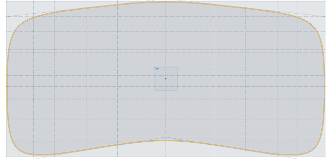
I also have no problem extruding this into a 16mm high 3D shape.
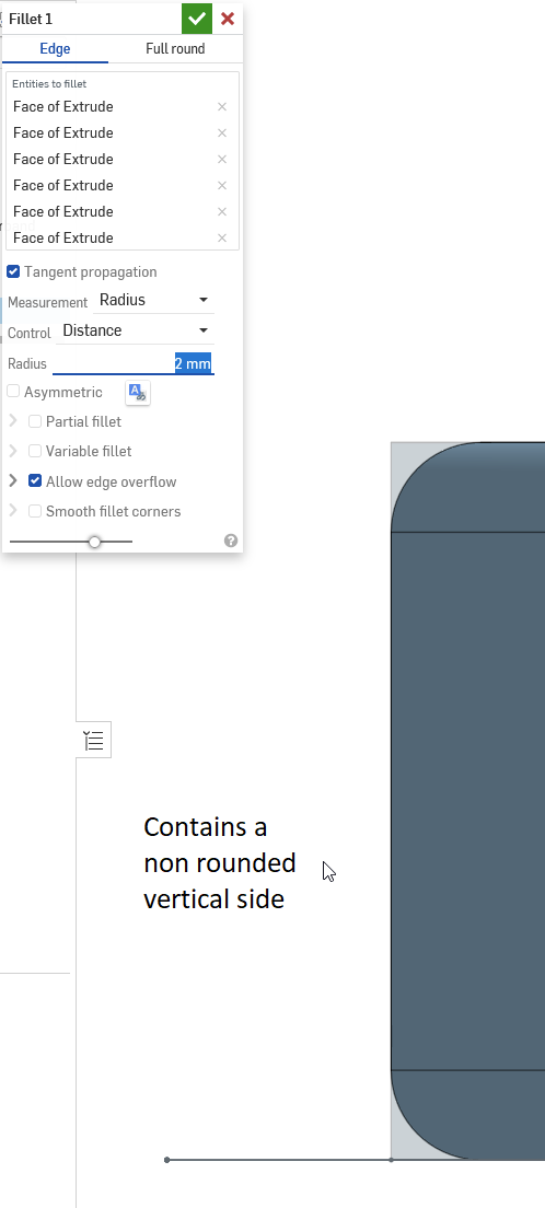
However, I would like the edge of the desktop to be rounded. I tried achieving this with the "fillet" tool, but it seems like this can only round a single corner (so a 90° part), while I'd like to round the whole edge (so a 180° part). I can round both corners, but to make the curve smooth (no straight lines) I then have to curve it with a diameter of the thickness of the desktop (16mm), which is waaaaay too rounded for this edge. If I use a diameter less than 16mm, only the corners are curved and not the whole edge. The curve has to be for the whole edge and quite soft (it may come out only about 3-4mm, so it should be a "circle-curve" with a diameter of of a lot more than 16mm). Not sure how to do that.
Below some screenshots showing what I mean:


My Wifes desktop
I'm not really happy with the 2D shape (in yellow) yet. My wife would like to integrate her arm support in the design of the desk. That is why there is this circle of 324mm cut out in the front / middle.

But the circle curve doesn't flow smoothly into the conic curve (see below) and I'm failing to fix this. I tried using other curves
than conic too, but those are even harder for me to flow from curve to curve smoothly.

I'm also not really happy with the shape in general. Perhaps I can fix this later changing the rounding amount here and there, perhaps not. But I think I need to learn how properly integrate that circle in a smooth manner first...
After this, also the extruding into a 14mm high 3D shape should be easy.
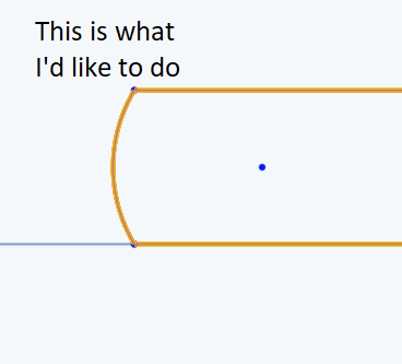
However, the edge for this desktop will a bit more complicated... I'd like the edge to make it seem like it is a very thin desk. So the edge needs a shape more or less like below

The above 2D edge shape should follow the entire 2D desktop shape (except perhaps a section of the back, so that it still has enough strength for a monitor arm, but lets keep that part for later ). After searching for a very long time, I still failed to figure out how to do this...
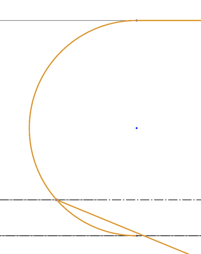
Also, as you can see in the screenshot above (this is the left part of the edge zoomed in a lot), I'm failing to make the half-circle transfer smoothly into the conic curve. It has a small "corner" in it.
My friends desktop
Didn't start on this one yet, but I don't expect issues with the shape (rectangle with rounded corners) of the desktop itself.
The edge should be the same as my wifes desktop. So same problem for that.
Outro
I Hope was able to make myself a bit clear and I hope someone can help.
Thanks a lot in advance!!
0
Comments
YOUR DESK
it would be nice to have the original desk shape to try to make what you ask for, but it may be that in the example of your wife's desk the function I used could be right for you in this project too.
YOUR WIFE DESK
here you can find a document I shared. I used spline instead conic curve for the arm support shape and for the edge shape. The use of spline allows you to set trangent constraints at the beginning and at the end of the curve:
https://cad.onshape.com/documents/049648a82c4e6b1f3f2d6929/w/ea9d7e4aed8c0b8712094444/e/b06db3e168137a1ba564215d
I hope this could be useful.
Looks like @Roberto_Verduci 's approach is exactly what I would try first, but if it helps at all, I thought I might chime in with a non Onshape comment... Its going to be expensive to CNC machine a custom underside. If cost is an issue, I might find what coving tools your machinist has in stock, so they can just run it all the way around.
Your profile can be done, but it will be more expensive than running around the edge with a tool, or set of tools they already have, and will likely need lots of sanding after machining.
Good luck
For "My own desk": you need to use the "sweep" tool to get the radius you desire.
I'll start by saying that I don't know the problem technically, but the sweep process in the two straight sections is solved by moving the curve of the edge drawn in the sketch away from the projection of the straight edge. Most likely, leaving the tangency generates a face error and this causes the entire process to fail.
I edited your original 2 mm quote to 2.1 mm
and this is the result:
As far as the circle part is concerned, you get an error because the sweep self-intersects.
So either you change the depth of the profile (the original quote of 75 mm) in order to eliminate the problem or, as I did in the document I published, first do the sweep on the desk without the circle and then add the circle machining.
I started with a quarter table, then mirror sketch and add another spline..
https://cad.onshape.com/documents/f01fdc508d2c5ed01ca37ede/w/c2ddb1e8cada19f649ce7ee5/e/0b900a3926b574bacce053a2
Rule #1 in product design is to design for the manufacturing process. Talk to the company with the CNC and find out what their capabilities are. Then come back and change your design to match, or find another company.
To be honest, one-off projects like you are designing for your family and your friend are probably cost prohibitive to send to a cnc shop, unless the owner is your friend and doing it for some beers. You are probably better off getting hardwood plywood from your local lumber dealer and cutting this by hand with a jig saw.
IMO:)
We specialise in extracting 2.5 axis CNC machining data (from a parametric library of designs curated through a configurator that runs in other CAD packages, like SketchUp - but that's another story). I guess our progress is different, because we do not own or operate the CNC machines. We create the data sets for others to go to machinists and workshops, and this means we don't know what machines they have, which CAM software they run etc.
Typically, 90% of workshops only have 2.5 axis CNC (here in the UK), so as @nick_papageorge073 suggests, they would take dxfs, and are essentially working in 2d, but they can control the depth the tool drops also, in the Z plane. Some machines and CAM software can ramp up and down also, running engraving procedures with a cone tipped tools. Although its possible do multiple passes ramping up to get any curved profile you need, not all CAM software can do this, not all operators can do it ! it might take a longer time to program, and it will take ages on the bed - I expect you will be charged per minute on the machine.
Up from this is 5 axis, where the head can tilt, and rotate. A lot fewer workshops have 5 axis over here. The only way to present the data is as a 3D step file or similar. It is placed in the stock and the CAM package works out all the passes and tool head rotations etc. To create a custom profile like I see here, it will do a number of passes, the more passes the better the resolution, then someone sands it off by hand I expect. It would not be cheap.
You will find workshops have several coving tools and cone cutters for table and desk edges - similar to as @dirk_van_der_vaart suggests. They can run these around the outside cut line, or have 2 or 3 tools they run in stepped passes to create a more gentle profile. But, it will not be the exact custom profile you have modelled. Or you can get profiling tools specially made. In the old days, a joiner would make a bespoke cutter on the grinder for the spindle moulder in order to match the profile of skirting in a room. You don't see this so much any more.
HPL is a high pressure laminate ? not sure how much wood is in it. Its more of a plastic appearance, and is primarily used for cubical doors in washrooms in commercial builds here. Its bomb proof stuff. Personally, I'd go for a Plywood, maybe a 24mm birch ply, with an oak veneer? you can get that off the shelf. Then CNC a rebate in the top surface and bond this stuff on flush to the surface, local to the work area.
https://view.publitas.com/forboflooring-uk/forbo-flooring-systems-furniture-linoleum-samplebook/page/2-3
Makes for a great desk surface, but maybe not in a school or high impact environment.
Good luck, let us know how it goes.
You spend some time to design a nice desk, no invest in some real nice material, a solid material
https://www.lxhausys.com/eu-en/products/himacs/aurora-bianco
Although things have been going slow, I've not been sitting still...I've now completed the 3D designs and spent quite some time finding a 5 axis CNC that can help us out (As you predicted, this wasn't easy, I found only 2 and they are not nearby - I still don't know the price though, that's the next step
Just to be clear: I've already acquired the HPL (High Pressure Laminate) material for the desks for free (my friend worked at the manufacturer). This is indeed the same material that they use for cubical doors in washing rooms or swimming pools, only the plates that I have are much thicker and actually meant for using as a design desktop material. When properly used, this is can be used for a very tough and durable desktop.
Here are the latest versions of all 3 desktops:
My desktop
https://cad.onshape.com/documents/c6b0d04bc102f3a914533702/w/44750f3e274a044e3d786c29/e/805d6bf6490b1fa1d08984f5
My friends desktop
https://cad.onshape.com/documents/467f4a7358f5de2576a29f37/w/9f051e82c46d0ea5b7b4c6c2/e/3c4298adcfad844fad90e01b
My wife's desktop
https://cad.onshape.com/documents/aaf548c541c9764180b26427/w/f998972bc769f5686430aa62/e/6fa28e73c3582f684d451e11
Hi everyone,
Just to let you know, the desks are finished in meantime (some while ago already). And I'm very happy with the result!
Thanks a lot to everyone for helping us get there!! It has been quite a struggle, but the end results is certainly awesome (still not sure if it was all worth it though ;) Even after finding someone who could CNC it, they still made many mistakes that took a lot of time and effort to get fixed).
Here are some pics: