Welcome to the Onshape forum! Ask questions and join in the discussions about everything Onshape.
First time visiting? Here are some places to start:- Looking for a certain topic? Check out the categories filter or use Search (upper right).
- Need support? Ask a question to our Community Support category.
- Please submit support tickets for bugs but you can request improvements in the Product Feedback category.
- Be respectful, on topic and if you see a problem, Flag it.
If you would like to contact our Community Manager personally, feel free to send a private message or an email.
Best Of
Re: CAM Program Options (If not CAM studio, what?)
The Education Enterprise does come with CAM Studio. But not 5-axis (Cam Studio Advanced).

Re: Standard Content: Inserting countersunk bolts or screws (multiple)
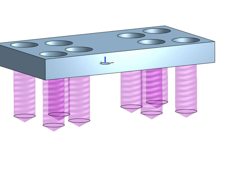
Yep, selecting the cone point is more awkward than it should be. It should be more automatic. Shift is essential. In your video you never highlight the cone. The 3 points you're cycling through are the top, middle and bottom of the cylinder - useless for countersunk screws. The countersink cone will show 4 potential mate points. You want the lowest one. Then of course you'll want to use replicate after that to add to a bunch of location.
 S1mon
S1mon
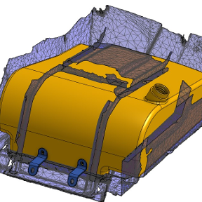
Re: Tolerance for Boolean Add Along Surface Edges?
@S1mon That is an interesting functionality.
Notice that every-where Onshape offers approximation 1e-5m is the default tolerance. That is for a reason.
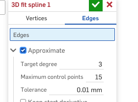
Here I'd recommend going an order of magnitude lower - at least 3.e-6m - to allow for downstream approximations. I have to also warn about some downstream issues. You can use the curve itself to trim the surface, but ruled surface or boundary surface built on this curve should not be used to trim the host surface. Such a trim would work most of the time, but has a potential to be unstable. That is true surfaces built on projected curve as well - they necessarily do an approximation. If you are doing split by surface - it is better to overbuild.
 lana
lana
Re: Improvements to Onshape - February 20, 2026
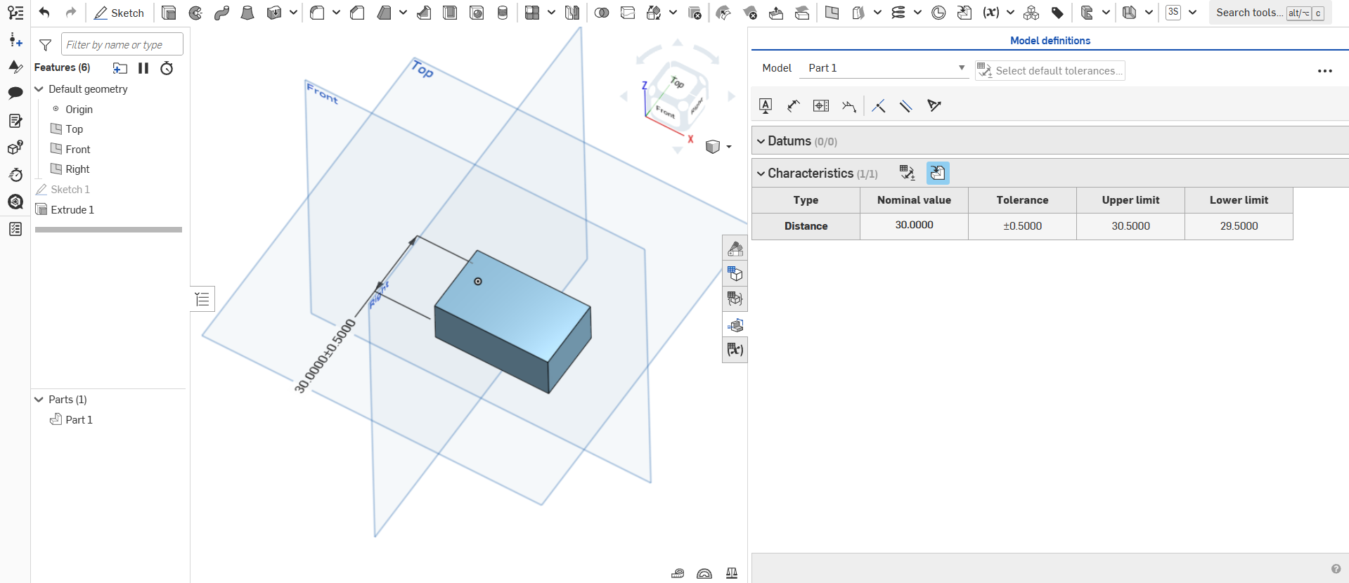
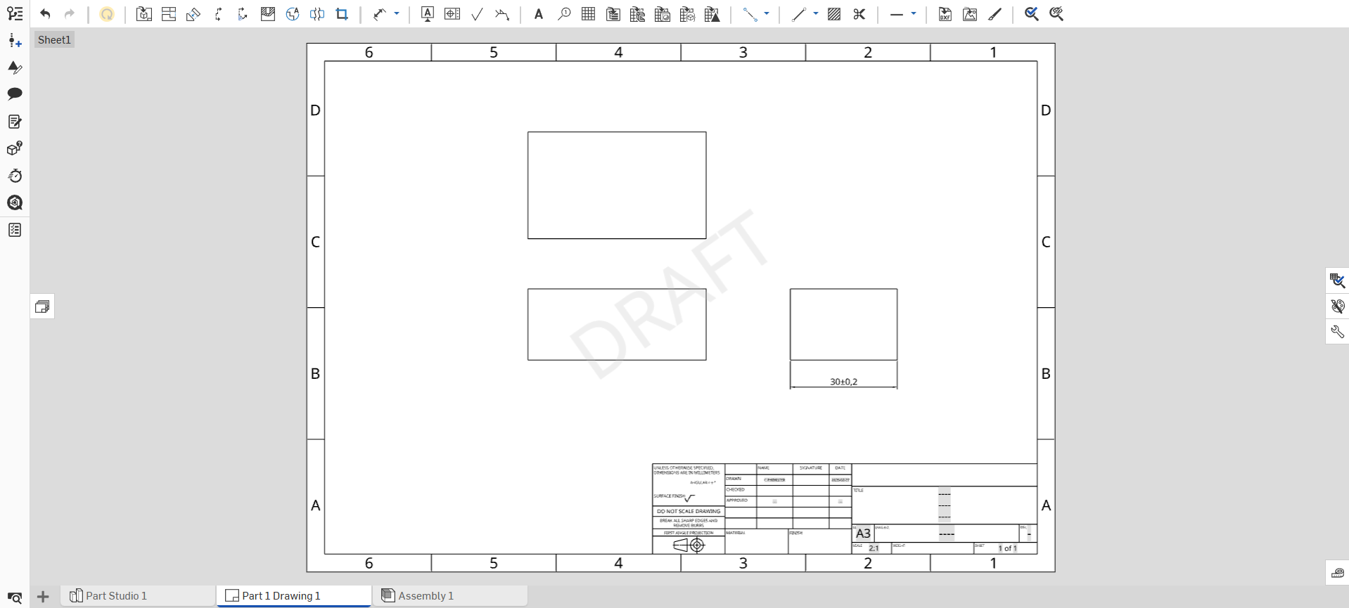
It's great to see Onshape adding MBD functionality and hopefully this will allow Tolerance Analysis functions to be added in the not too distant future. However, before that, I would hope that we would see an update that allows us to show dimensions and geometric tolerances that have been added to the 3D part, within the drawing. As it stands, the concept of "a single source of truth" falls down, when you can create a part and associated drawing with different tolerances applied to the same dimension.

Re: Improvements to Onshape - February 20, 2026
It would also be great if you could make not just MBD but normal sketch dimensions and other features like fillets and chamfers show up automatically in drawings like you can in Creo. I am a former Creo user and this is one of the features I miss in Onshape, it speeded up the tedious work with drawings. Onshape is not yet as advanced as Creo, but I hope PTC will not stop developing/keep it simpler to avoid canibalizing on more expensive Creo licenses.
https://www.youtube.com/watch?v=VSpv2KQrwvY
https://support.ptc.com/help/creo/creo_pma/r12/usascii/index.html#page/detail/dims_about_showing.html#wwID0EHIHU
 PeterM
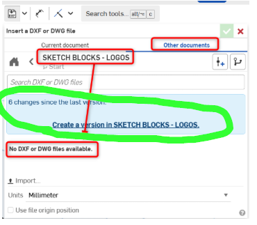
Re: Why Can't I Use DXF's From Another Part Studio?
The answer is right there: you need to create a version in order to reference something from another document:

What is the official 3D sketch feature of Onshape?
Hello,
I actually come from SolidWorks background. I cant find the official 3D sketch feature of Onshape.
It would be helpful if anyone could help.
Thank you.

Re: Custom Feature: Amalgam Tag and Amalgamate
@wille_j Thanks for sharing the video. I know we've talked about the methodology in the past, but it was good to have it all right there with images to support. I've used super derive for similar things for years, like making the holes needed for a bearing and retaining ring, but the more I think about the method the more sense it makes to me. I think Amalgamate takes it one step farther, which is terrific! BTW, I'm working up a version of Hole that makes positive bodies for use with atoms/molecules, since the hole attributes and cosmetic threads will transfer through a boolean operation. Should have it available soon.

Re: revolute mate / tangent mate interactions
cylindrical lets motion in z axis and rotation about z.. revolute only allows rotation about z happen. if you're model isn't perfect then there are cases where allowing motion along z will allow that motions to happen the way you want. In this case it looks like your pistons are slider mates and your connecting rods are revolute mate to the crankshaft. So your crank is automatically locked along the axis by definition of the slider and revolute combined.. If your crank shaft isn't aligned perfectly with where your pistons need to move… assigning a revolute to the end it will break it because your crank to rod revolute mates already lock in that direction and its trying to shift the crank to line up with the block.. setting the crank to rod mates to cylinder would have also likely allowed you to assign a revolute mate to the crank and block.. Clear as mud?
 MDesign