Welcome to the Onshape forum! Ask questions and join in the discussions about everything Onshape.
First time visiting? Here are some places to start:- Looking for a certain topic? Check out the categories filter or use Search (upper right).
- Need support? Ask a question to our Community Support category.
- Please submit support tickets for bugs but you can request improvements in the Product Feedback category.
- Be respectful, on topic and if you see a problem, Flag it.
If you would like to contact our Community Manager personally, feel free to send a private message or an email.
Best Of
Show & Tell - Features from a mechanical designers point of view
Eventually I'd like to automate a bunch of aspects of my day-to-day mechanism design work. I have a couple projects I'd like to do with FS, but to get up to speed I decided to do a hole wizard, but from the perspective of a designer rather than a draftsman.
So my specification goes something like this:
- A screw joint holds two pieces together, preferably under compression.
- The compression load is dictated by the design requirements.
- The screw thread, depth, and support web follow from the compression load and choice of materials.
So my hole wizard should take as inputs the two parts to compress, the materials, and any cosmetic requirements I have. That's it.
Optimization of screw thread, thread depth, web thickness, and screw distribution across a generic surface is a little ambitious for a 2 day project so I'll let that be an input for now.
So, the feature takes:
- 2 parts,
- N sketch vertices (hole axis inferred from vertex plane normal),
- thread to use, (specs pulled from standards)
- thread engagement length & support web thickness, (specs chosen by designer or optimization)
- whether to prefer blind holes,
- how to choose screw length.
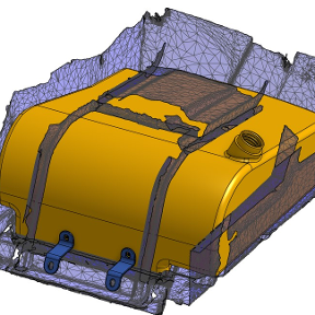
I started with a pair of solids complicated enough to be interesting and capture a reasonable amount of the design space.

Holes are defined by sketch point locations. Restrictions unrelated to the task at hand are a pet peeve of mine so there can be any number of points on any number of planes in any orientation. Each point, together with the plane it is drawn on, defines a hole axis.

Hole geometry is defined by the parts that have the holes in it so it does not matter where the planes are relative to the parts.

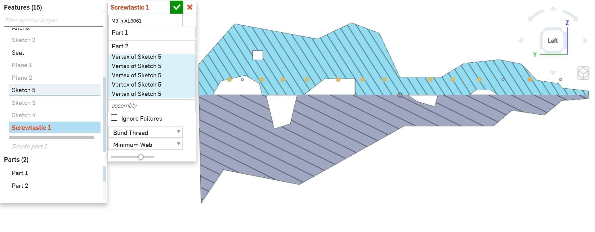
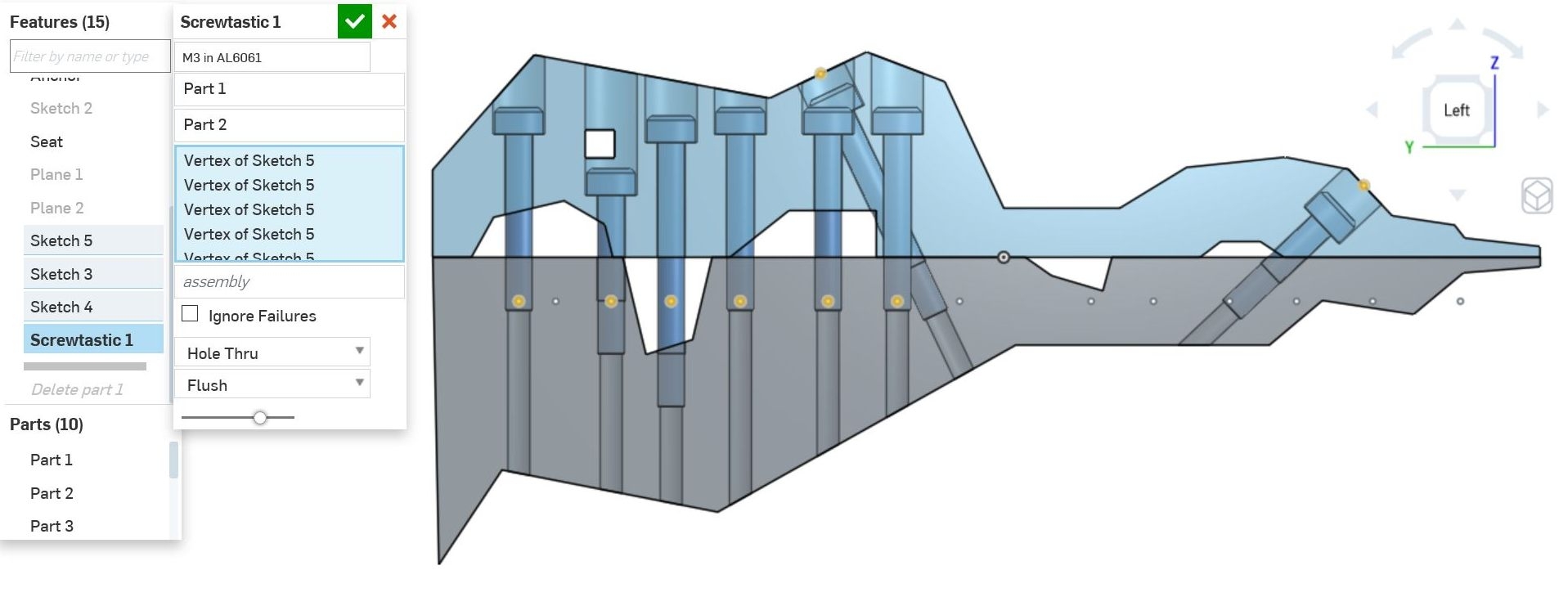
Then you select the two parts of the join, and the locations for your screws. In the following image one point caused an illegal condition (on the far right highlighted in debug orange) which if you hover for the error will tell you that there is not enough material for the required 6mm of thread engagement.
Finally you can give it info on whether to force the use of blind holes and how to choose the screw length.
That's it. The feature
- inspects the parts along each screw axis,
- verifies enough material for the requested thread engagement,
- punches blind holes through if they are close enough to cause dimpling on the back-side of the part,
- chooses the closest screw length from the list of standard lengths that will give as close to the target web thickness as possible,
- and (this is important) instantiates the screws. Why would I ever want a screw hole without a screw?

A different goal for the screw length that the designer might want is to minimize the counterbore. (It says flush, but that's mislabeled from another unimplemented mode that increases the thread engagement as needed to make the heads truly flush). Not shown here is the fact that the minimum web thickness is the dominant requirement, so the head will stick up above the surface if necessary to maintain that.
If there is not enough material in either part, it tells you and fails the rebuild. A full implementation of this feature would add threaded inserts and load distribution washers as necessary.
If minimizing part count is important, it will find a screw length from the available lengths that will fit all the material conditions. Notice I had to de-select some of the right side holes to find a solution. The errors guide you in this.

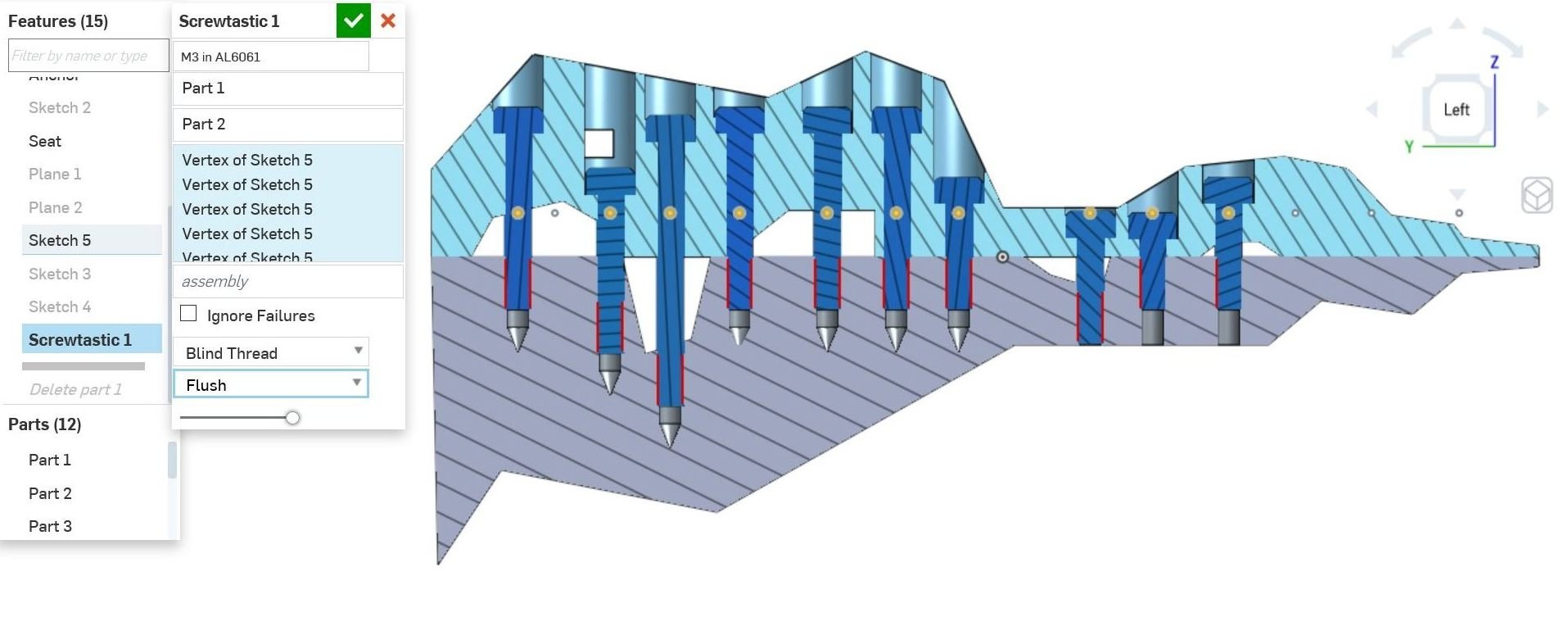
Sometimes thru holes are preferred for manufacturing purposes. No problem.

Again, the position of the features along the hole axis is defined by the parts we are seating in, not the location of the specification point. In the following I made no other change than flip the location of the points sketch plane. It rebuilds the same. As it should.

Here I swapped the two joint part selections.
As I mentioned before, the axis direction is taken from the plane the point is in. I added two points above the centerline, resting on the respective angled surfaces. Will it build !?!?

Yes of course. (The angled screws lie in a different plane and don't intersect the vertical ones). 'Same length' is selected so you can see it allowed the right angled screw to pop up out of the counterbore to do this (thread engagement is constrained to not change). BTW: The tap holes have a spotface added for manufacturing if the surface is not normal to the screw axis. The whole feature is restricted to subtractive processes. It won't add a boss under the head for instance.

Swapping the joint parts again.... I think the allowed screw lengths in this range are 20,25,30mm so it's having a hard time finding a length that fits nicely on the right.

With the equal length constraint relaxed, it selects shorter screws for the right side.
Return to blind holes and minimum web thicknesses.

I found it hard to grasp the data model until I read a parasolids document detailing the topology terminology. I'm not sure I took the best approach in analysing the geometry for the heuristics. I'm making heavy use of temporary solid tools and booleans.
I'll release the code for comment as soon as I clean up the unintelligible bits from the final couple hours.
I had performance problems while developing, but they are server issues rather that feature building issues. Rebuild from unsurpress when the server is behaving is about 2 seconds for the above model.
I'm still trying to understand the best way to import/export data. Dumping featurescript compatible maps from my other tools (Python and Lua mostly) seems like the way to go. Like others, I wish the import could follow workspaces as well as versions so that simultaneous development of library and working documents is not so painful to keep synced.
The code is about 800 lines with lots of cut and paste that could be compressed with functions. Two conditions which would need additional heuristics are large voids in the middle of a part, and having both sides of the joint be the same part (like a shaft clamp).
That's it for the show & tell. I'll document the heuristics if I can get the time. In case I don't....
This shows the tools used to understand the extents of the material each screw thread and screw head will be embedded in.
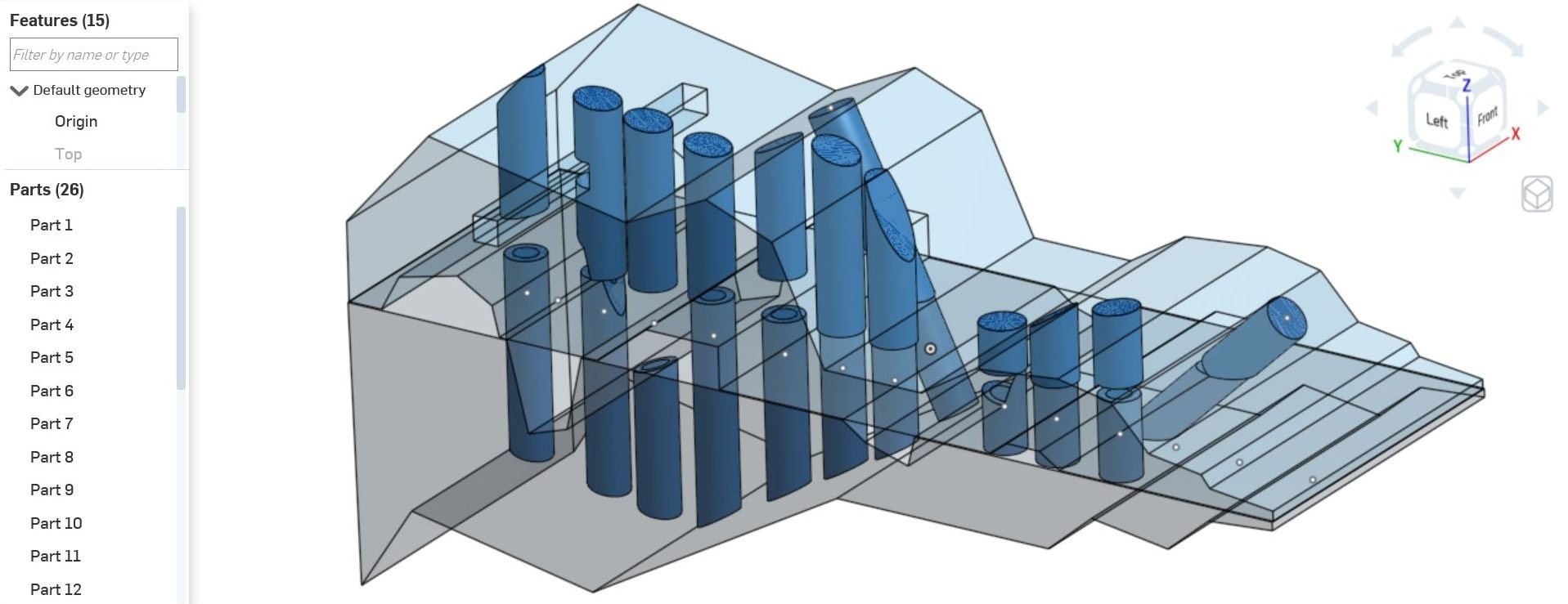
This shows the tools used to verify that the final thread location and final web (head) locations have the required material and that's it is unbroken (I compare the volumes of what's expected with what I measure.

Most of the heuristics are implemented by sampling the world using boolean intersection with tools of relevant shapes. However I also do some goofy face clustering in there too. The funky part shapes exposed lots of insufficient approaches as well. Had I used flat, constant thickness parts I would have ended up with something much less robust and not learned as much either.

Re: Vehicle coordinate system
My description of the common aerospace system may have been too specific. Aerospace does generally use a right-hand coordinate system. Most commonly the coordinate systems for aircraft design use the x-axis along the aircraft longitudinal axis (nose-to-tail direction). However, depending on the project it is common to see the direction as either positive aft or positive forward. There are also some variations between disciplines within aerospace where aerodynamics and flight dynamics design are in one coordinate system and mechanical design is in a different system.

This just reinforces the need to have flexibility to set things up for the company and/or a project with the ability to override defaults when needed.

Re: Beyond system limits - imported DXF
I ran into this as well. I had an object that was created in AutoCAD and when I opened the file, the object was at a coordinate of like 25000,25000 so I moved the object closer to 0,0 and resaved. Worked.
Re: How to create flute with varying top fillet
I think using a sweep to create the flutes might not work in this case. Try a loft between two slightly different profiles. Something like this:
https://cad.onshape.com/documents/a12aef7c34be087095f48b53/w/565e36a3243c7c973e090ef2/e/6d60f594de25302a247ae9c9


Re: Sheet metal cone
@aaron_harris672 It looks like you have some twisting going on in the loft which would cause compound curves. Current sheet metal functions do not like this. I updated the sketches and used the thicken command in sheet metal to have your loft flatten in sheet metal. Here is the link. Hope this helps.
https://cad.onshape.com/documents/2f24160b17fd32e9491671e4/w/fea14f476f7c22e446cb55b1/e/247159b2e7c66a593fd55ab9

Re: How do I add buttons to a UI window like the ones in Routing Curve?
YEEEHAAAW thanks for this legend!

Re: LSP support for FeatureScript?
There are a lot of features in VS Code which won't be supported in Onshape. Besides the many features it supports which developers expect and appreciate, it is just fast and lightweight. I have read in the forums that the FS editor can become quite slow.
I saw the old discussion in 2019 and I expect a lot has changed since then. What we would get with LSP support for FS which any IDE that supports LSP offers. There are many tools which support LSP.
https://microsoft.github.io/language-server-protocol/implementors/tools/
I would expect the IDE to be able to reference the dependencies just like JS does with npm or even Deno which is even better. However the Onshape brings in dependencies would be supported by an extension. It would also be responsible for syncing changes. The LSP support would just be a major bonus to provide the rest of the features that developers expect. Then there are other extensions which are available in IDEs like VS Code which can be invaluable and would not require Onshape any investment to support.

Re: Can't figure out how to make a tapered symmetrical open donut
Thank you! this is exactly what I was hoping for. I will dig through this to learn how you did it.
 St_Sh_
New Part Spacing Featurescript
Hey all,
I've made a custom FS that separates parts an exact distance from each-other relative to a selected plane.
took me a while so happy to share my little passion project milestone. This is particularly useful for separating parts ready to be nested / nesting:

The parts space in the order they are selected, in other words for every part you select all previously selected parts move together:


Note that in the second image part 6 and 5 (Long part and left large part) are selected first and so move left together once the right part is selected.
The script is indeed very process heavy (laggy) as there is no way to perform the necessary processing without also creating and deleting entities as reference using featurescript. However it is quiet powerful:

I like this example as it would be very time consuming for me to space these parts using sketches as references but using this script it takes just a few seconds. Parts don't have to be flat either all that matters is you select the plane you want things to be spaced on:

Merry Christmas everyone. Let me know if this helps anyone, if there's any bugs or if you want an explanation on how it works as it's a little complex.
Here's the Featurescript Link !!!
You can ignore all the other tabs in my doc. I'm working on a pretty big project.