Welcome to the Onshape forum! Ask questions and join in the discussions about everything Onshape.
First time visiting? Here are some places to start:- Looking for a certain topic? Check out the categories filter or use Search (upper right).
- Need support? Ask a question to our Community Support category.
- Please submit support tickets for bugs but you can request improvements in the Product Feedback category.
- Be respectful, on topic and if you see a problem, Flag it.
If you would like to contact our Community Manager personally, feel free to send a private message or an email.
Best Of
Re: Consultation on how to create a sweep between two parts in different plains
You might find loft with a path helpful. but you may need to add an additional profile or 2 at strategic locations to control the tilt that will be inevivtable when it joins the ball tray at the bottom
 MDesign
Re: Consultation on how to create a sweep between two parts in different plains
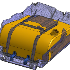
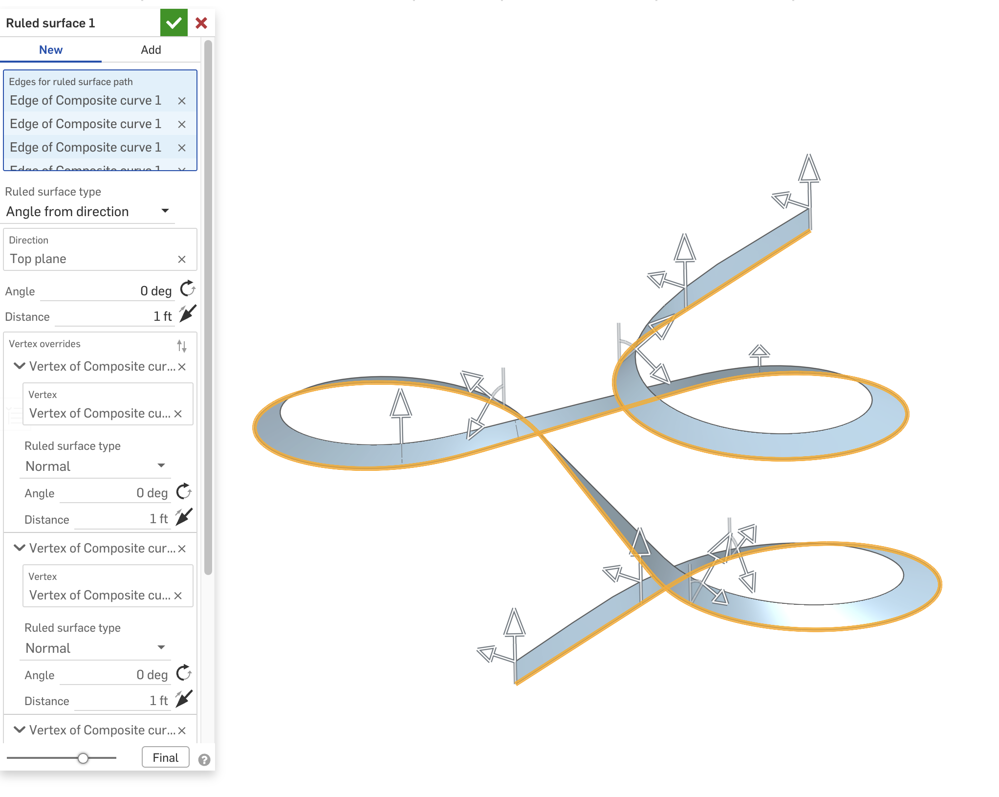
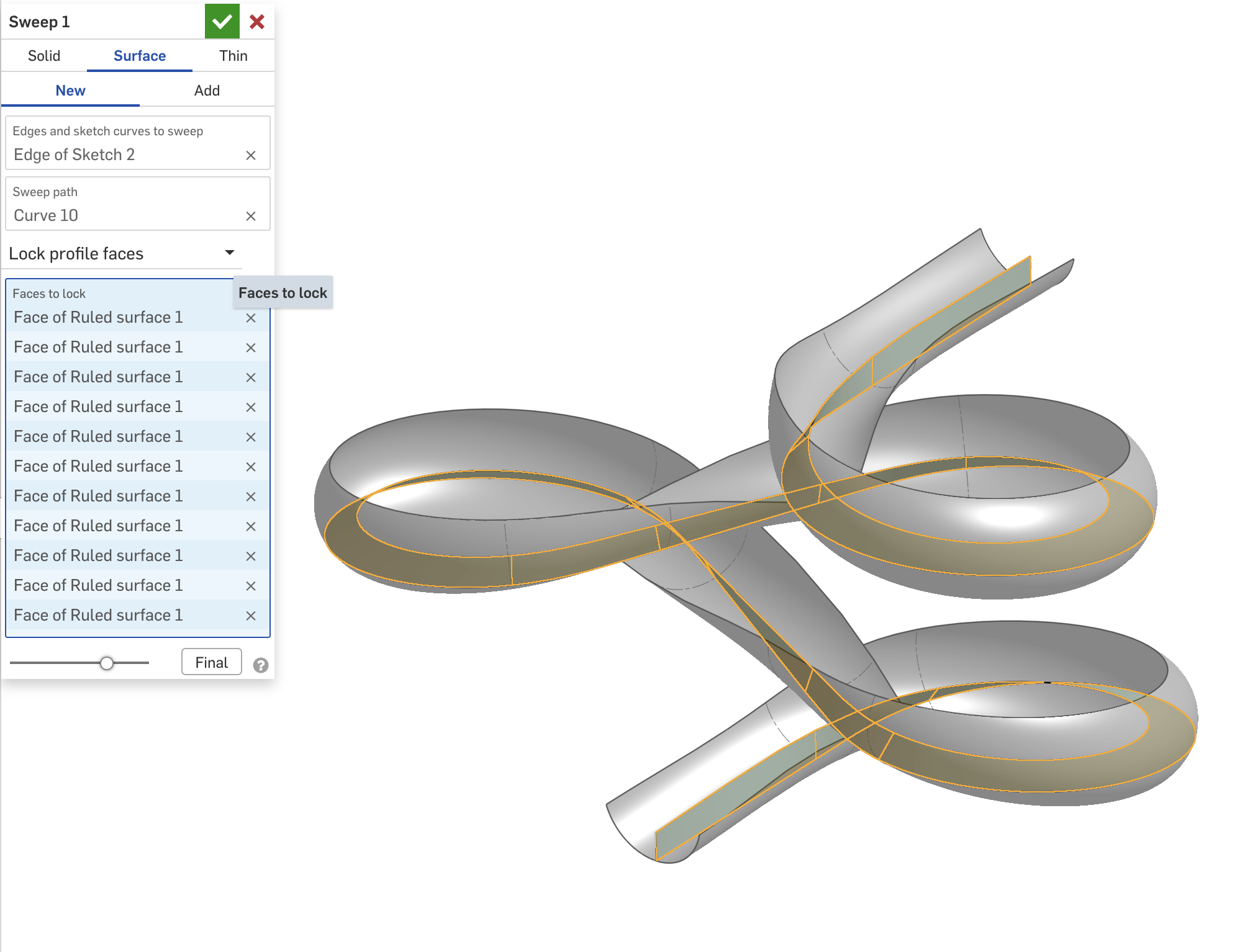
If I understand the question, you can use a Ruled Surface to create a reference face so you can control the orientation of the sweep using "Lock profile faces". Here's an example model I made a while back.

Demonstration: Enhanced Debugger FeatureScript
Yes! The debugger can actually be smooth to use. And with this little trick, you can surgically Debug!
Essentially this involves incorporating the → 'arrow' syntax, and a standard use of Lambdas to bypass the ever abundant "context". Some other functions for println, and colored Debug are also included.
Here are the snippets for easy access. Though the actual document is fully commented.
var c is Context = context;
var clrs = [DebugColor.RED, DebugColor.GREEN, DebugColor.BLUE, DebugColor.CYAN, DebugColor.MAGENTA, DebugColor.YELLOW, DebugColor.ORANGE]; // DebugColor.BLACK

var d = s => { c -> debug(s); return s; };
var dc = (s, clr is DebugColor) => { c -> debug(s, clr); return s; };

var p = (arr is array) => println(arr -> foldArray((a, b) => { return a ~ "\n" ~ toString(b); }));
var pl = (s is string) => println("-=-=-=-=-=-=-=-" ~ (s != "" ? " [" ~ s ~ "] -" : "" ) ~ "=-=-=-=-=-=-=-");
 deDev0
Re: Scanning Service?

Re: Feature scripts
I fixed a few issues in your custom table… try this now: https://cad.onshape.com/documents/bcb49665ab815049abfc33a0/w/f05bf45252300e5c0fbe04b3/e/14f645ee405326a00c3fd52d
You had missed a few things with the maps references needed to be made to the key e.g. densities[material.key]
Also your helper function computeMasses needed to be outside the custom table function…

Re: Demonstration: Enhanced Debugger FeatureScript
Nice to meet same arrow syntax abuser as myself 😅
Using for long time an overload of debug function which takes value as first argument and context as second one and returns value.
export function debugReturn(value, context is Context)
{
debug(context, value);
return value;
}
 Konst_Sh
Re: Featurescript Dev Paid Contract: BOM Auto-Kitting Featurescript
Thank you everyone for responding! I'll be reaching out over the next few days! To save future people's time, I think enough people have reached out that this is closed for now!
Re: Make extrude removal stop before walls get too thin while maintaining a consistent cross section
Hello @S1mon, thank you so much for your quick reply. I was able to come up with another solution inspired by your idea which required less workarounds for the difficult geometry of the foil profile.
Thank you also for fixing the loft at the end by making it have a normal to profile end condition - I was not able to do this before but with your changes I was able to.
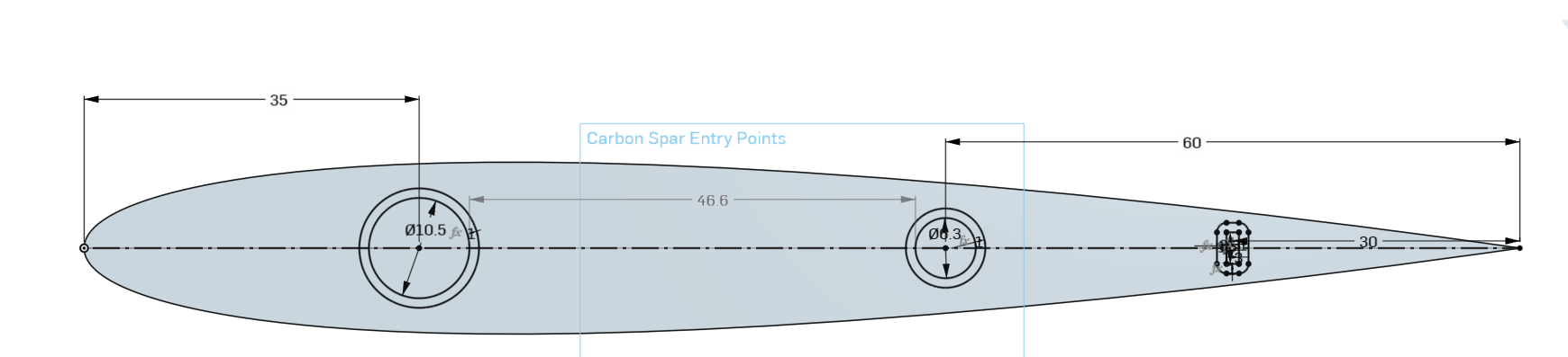
I first tried to use the HAVF tool but this gave me slightly assymetrical foils which caused some issues. This could have been mitigated but I decided to keep with what I was already using.
Then I edited the Carbon Spar Entry Points sketch to add the minimum boundary around it in the sketch rather than making the minimum boundary in the End Loft. I extruded surfaces from each of these minimum boundary boxes that I made in the sketch and also make an extrusion in new mode for each of the spars like your document. I made the extrusions go Up to Next rather than up to the end vertex as this worked better for me. These are labelled Spar Template Tool and Spar Minimum Wall Template Tool.
I then made a sketch on the chord plane of where the Spar Minimum Wall Template Tool intercepted the outer surface of the part. This sketch was labelled Spar Minimum Wall Thickness Intercept. I then did one split for each of the spars on the point of intersection. Then just a boolean subtract to make the spar holes.
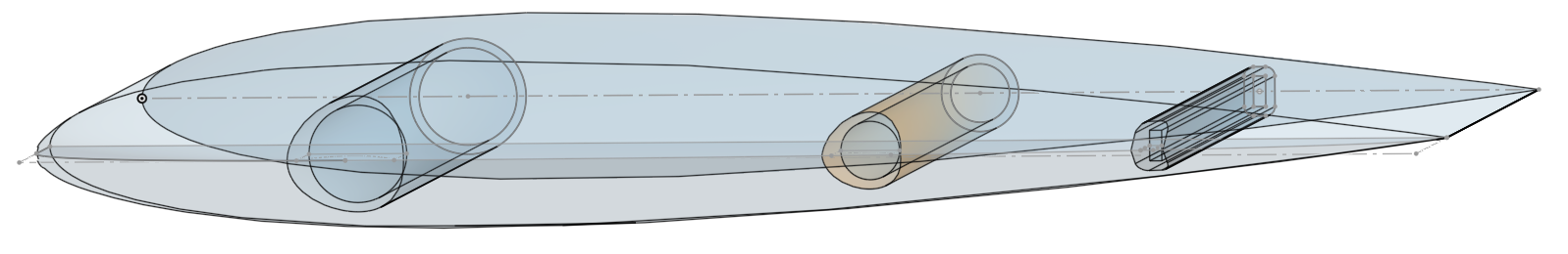
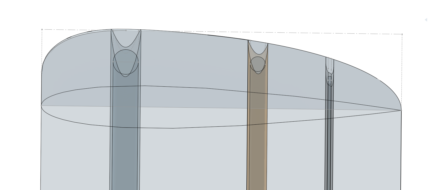
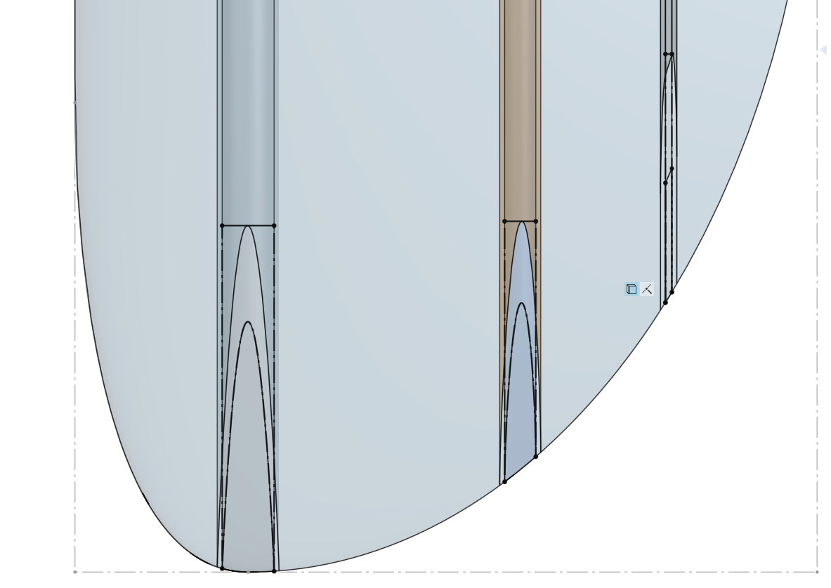
I just have a few quick questions about some of the issues it seemed that you had to work around in your document. For the offset surface to work, you had to cut the round end off and do some face blends otherwise it would create errors - is this a problem specific to foils? What causes this issue?
Also, when I was playing with the shape of the End Loft, I found that if I used the condition Match Curvature it would not allow me to use the Use function on the spars in my Spar Minimum Wall Thickness sketch. It works just fine with Normal to Profile though. Is this related to the problem above? What causes this?
Thank you so much.
Re: New Custom Feature: Segmented Pipe
sorry, forgot to make public:
https://cad.onshape.com/documents/b08acb3b79f42f8e5008740a/w/d1a55166098ecdeb1b2675e0/e/5f0750551e96fa080dcb00a3