Welcome to the Onshape forum! Ask questions and join in the discussions about everything Onshape.
First time visiting? Here are some places to start:- Looking for a certain topic? Check out the categories filter or use Search (upper right).
- Need support? Ask a question to our Community Support category.
- Please submit support tickets for bugs but you can request improvements in the Product Feedback category.
- Be respectful, on topic and if you see a problem, Flag it.
If you would like to contact our Community Manager personally, feel free to send a private message or an email.
Make extrude removal stop before walls get too thin while maintaining a consistent cross section
 twister279
Member Posts: 6 ✭
twister279
Member Posts: 6 ✭
Hello all,
I am trying to make a leeboard hydrofoil model on this document: https://cad.onshape.com/documents/40a09d2b7dbc0e96f864de60/w/9b820e6caf97b342e0b34d33/e/e4addd4030400b4f4e982b63?renderMode=0&uiState=687bf140abce191eed0df80b
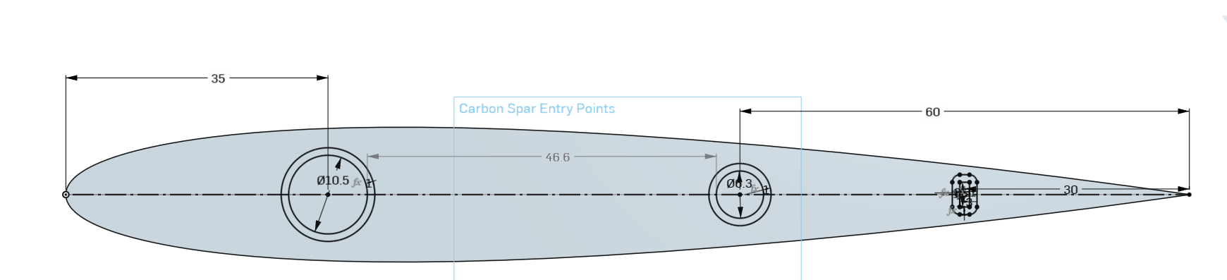
This will be 3D printed with carbon fibre spars inside it, and I have been struggling to make the holes for the carbon fibre spars. The basic idea is to use the sketch Carbon Spar Entry Points to make holes that will allow a carbon fibre spar to be entered into the hydrofoil.
Because the hydrofoil tapers at the end, the carbon spars cannot run the full length of the hydrofoil as they would be too thick to fit in the tapered area. So I want to make the hole for the carbon fibre spar stop with a flat bottom (which up to face/next does not give) before the walls around the carbon spar would get too thin.
When I say "too thin", I mean that I would not want any part of the spar to be within x mm of the outer shell in any axis (with the exception for the flat top of the hydrofoil where the spars will enter into it). For now, we'll say 2mm from the outer shell of the hydrofoil is the minimum wall thickness.
So far I have tried extrude remove with up to face/next and offset, the hole tool, move face and thicken - I know that some of these will be completely the wrong tool but I have just been playing to see what works. I'm sorry if this is an already answered question but Googling this has yielded no results probably because I'm not able to describe it in only a few words.
Thank you so much for any help!
Best Answer
-
twister279
Member Posts: 6 ✭
Hello @S1mon, thank you so much for your quick reply. I was able to come up with another solution inspired by your idea which required less workarounds for the difficult geometry of the foil profile.
Thank you also for fixing the loft at the end by making it have a normal to profile end condition - I was not able to do this before but with your changes I was able to.
I first tried to use the HAVF tool but this gave me slightly assymetrical foils which caused some issues. This could have been mitigated but I decided to keep with what I was already using.
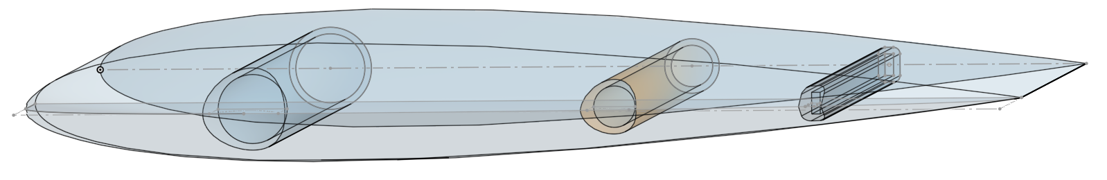
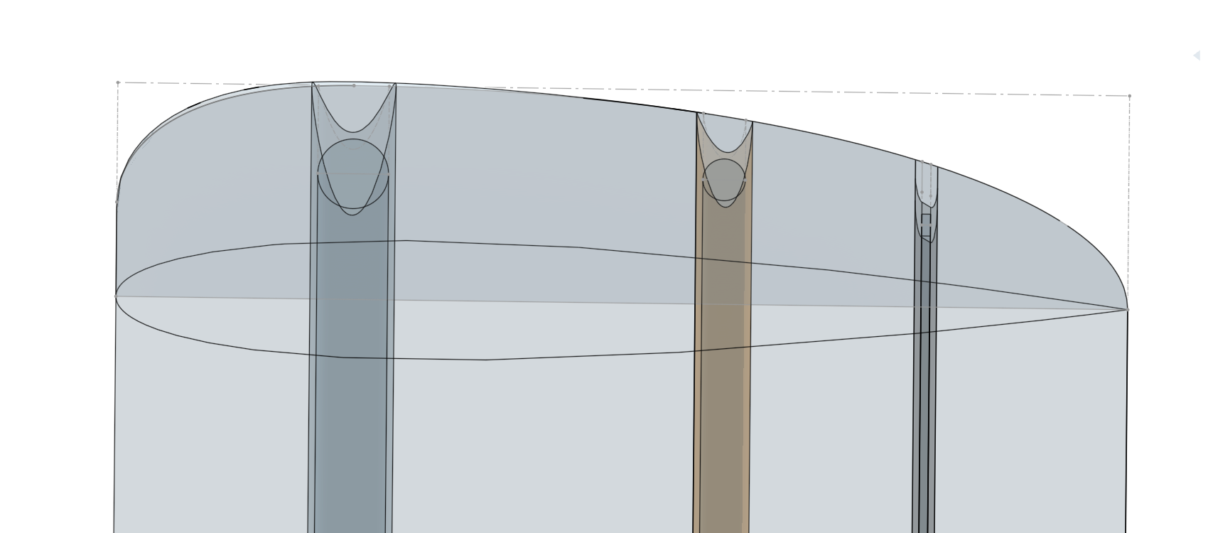
Then I edited the Carbon Spar Entry Points sketch to add the minimum boundary around it in the sketch rather than making the minimum boundary in the End Loft. I extruded surfaces from each of these minimum boundary boxes that I made in the sketch and also make an extrusion in new mode for each of the spars like your document. I made the extrusions go Up to Next rather than up to the end vertex as this worked better for me. These are labelled Spar Template Tool and Spar Minimum Wall Template Tool.
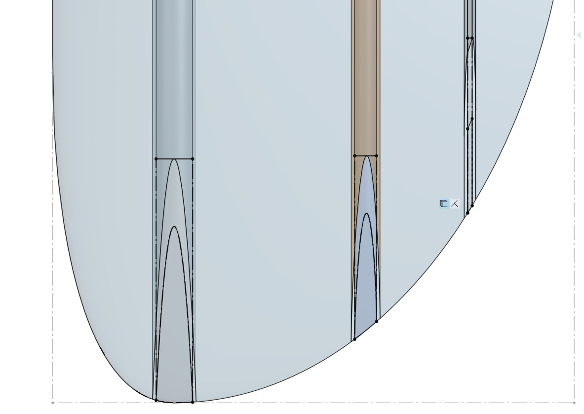
I then made a sketch on the chord plane of where the Spar Minimum Wall Template Tool intercepted the outer surface of the part. This sketch was labelled Spar Minimum Wall Thickness Intercept. I then did one split for each of the spars on the point of intersection. Then just a boolean subtract to make the spar holes.
I just have a few quick questions about some of the issues it seemed that you had to work around in your document. For the offset surface to work, you had to cut the round end off and do some face blends otherwise it would create errors - is this a problem specific to foils? What causes this issue?
Also, when I was playing with the shape of the End Loft, I found that if I used the condition Match Curvature it would not allow me to use the Use function on the spars in my Spar Minimum Wall Thickness sketch. It works just fine with Normal to Profile though. Is this related to the problem above? What causes this?
Thank you so much.
1
Answers
One challenge is that you're using the Profile Generator which creates very complex curves which are very hard to work with. I would highly recommend trying the HAVF feature:
https://forum.onshape.com/discussion/24730/new-custom-feature-havf-profiles-standard-airfoil-profiles
For now, I cleaned up the curve you created with Profile Generator using the Edit Curve Approximate function. Then I offset the tip surface (after trimming the tip and adding some radii to the front and rear so that the offsets would work). This allowed me to create a reference cut in a cylindrical tool which I used to trim its length and then I subtracted from the wing.
There's a variable which controls the offset distance for the minimum wall. It will likely fail at some values because of the challenges of offsetting the wing surfaces.
There's probably a bunch of ways to solve this, but hopefully this gives you some ideas.
https://cad.onshape.com/documents/7d63b744f5205987cf635ae7/v/ccb08808b8b03ae17e0adcc5/e/5b9d5886443430dbda1e3b52?showReturnToWorkspaceLink=true
Simon Gatrall | Product Development, Engineering, Design, Onshape | Ex- IDEO, PCH, Unagi, Carbon | LinkedIn
I realised that the link does not go to the branch that I was working in, so here is the part that I have worked on: https://cad.onshape.com/documents/40a09d2b7dbc0e96f864de60/w/2820e3bbc7d56a00d40e93b4/e/e4addd4030400b4f4e982b63
Hello @S1mon, thank you so much for your quick reply. I was able to come up with another solution inspired by your idea which required less workarounds for the difficult geometry of the foil profile.
Thank you also for fixing the loft at the end by making it have a normal to profile end condition - I was not able to do this before but with your changes I was able to.
I first tried to use the HAVF tool but this gave me slightly assymetrical foils which caused some issues. This could have been mitigated but I decided to keep with what I was already using.
Then I edited the Carbon Spar Entry Points sketch to add the minimum boundary around it in the sketch rather than making the minimum boundary in the End Loft. I extruded surfaces from each of these minimum boundary boxes that I made in the sketch and also make an extrusion in new mode for each of the spars like your document. I made the extrusions go Up to Next rather than up to the end vertex as this worked better for me. These are labelled Spar Template Tool and Spar Minimum Wall Template Tool.
I then made a sketch on the chord plane of where the Spar Minimum Wall Template Tool intercepted the outer surface of the part. This sketch was labelled Spar Minimum Wall Thickness Intercept. I then did one split for each of the spars on the point of intersection. Then just a boolean subtract to make the spar holes.
I just have a few quick questions about some of the issues it seemed that you had to work around in your document. For the offset surface to work, you had to cut the round end off and do some face blends otherwise it would create errors - is this a problem specific to foils? What causes this issue?
Also, when I was playing with the shape of the End Loft, I found that if I used the condition Match Curvature it would not allow me to use the Use function on the spars in my Spar Minimum Wall Thickness sketch. It works just fine with Normal to Profile though. Is this related to the problem above? What causes this?
Thank you so much.
Offsets are generally limited to their minimum curvature plus some tolerance. There are a few special improvements where simple fillets will disappear when the offset is greater than their radius, but generally surfaces with tight curvature areas are hard to offset. Trimming off the problem areas can make an offset possible.
I'm not sure I fully follow the issue with the Use function in the sketch. There are times where a 3D curve has some weird issue when you try to project it to 2D in a sketch.
Simon Gatrall | Product Development, Engineering, Design, Onshape | Ex- IDEO, PCH, Unagi, Carbon | LinkedIn
Hello again,
That's interesting, I'll need to research a bit more for the offset tool.
As for the issue with the use function, I think this is just a case of the "weird issue" that you described where curve projection doesn't work. I just thought that it was really odd that changing the loft end condition would break the curve projection.