Welcome to the Onshape forum! Ask questions and join in the discussions about everything Onshape.
First time visiting? Here are some places to start:- Looking for a certain topic? Check out the categories filter or use Search (upper right).
- Need support? Ask a question to our Community Support category.
- Please submit support tickets for bugs but you can request improvements in the Product Feedback category.
- Be respectful, on topic and if you see a problem, Flag it.
If you would like to contact our Community Manager personally, feel free to send a private message or an email.
Best Of
Re: Connect two extruded solids (cylinders)
Hello Matteo. Assuming the Front plane is in the center of the part, create a sketch on that plane, making use of the sketch's Use tool to capture the relevant surface edges of the shapes to connect the rib to. Draw a diagonal line between the captured lines to create a closed surface. Extrude that shape to the desired thickness, making sure 'symmetrical' is checked off in the extrude dialog. - Scotty

Re: Connect two extruded solids (cylinders)
Rib Tool works well.

Make sure the sketch for the rib is down a bit from the top or the edges will run past in this situation and throw an error.


Re: best way for loft sections between two changing size faces in different parts


ah, I see. Well how about this then. wrap the sketch to the first surface then transform that surface to a new surface with a scale factor and displacement via mate connector. then just create all the lofts
 MDesign
Frame Cut Lists K-Factor is 1?
I have been looking at cut list properties a little closer lately and noticed that the cut list tool assumes that the outside dimensions of any rolled segments are representative of the final straightened segments of frame length. Recently we had some rolled round tube come out of the shop oversized and the fabrication team had to rework the parts, and only after I've been digging into the featurescript implementation of cut lists did it occur to me that the dimensions given by the table might have been the cause for the out of spec parts. Wouldn't it be more appropriate to use the mid-line of the frame for rolled segments for a closer approximation of how frames deform when put through a rolling operation? Ideally the ability to specify a k factor for particular bends would be best but .5 is surely a better stab than 1.

Re: Aligned measurement issues
You need to drag it further away. Try zooming out.
There's an improvement request logged to make drawing dimensions work the same as sketch dimensions.
Onshape Boston User Group: Designing What’s Next
Join us at PTC HQ on Wednesday, July 16 for an evening of hands-on learning, meaningful conversations, and a look at what’s ahead in product design.
Whether you’re just getting started or already deep into your Onshape journey, this is a great opportunity to:
- Learn practical tips to improve your Onshape workflow
- Network with other engineers, designers, and innovators
- Show off your latest project or get feedback from the community
Event Details:
Date: Wednesday, July 16
Time: 4:00 PM – 5:30 PM
Location: 121 Seaport Blvd, Boston, MA
Agenda:
4:00 – Check In and Networking
4:30 – Naya Presentation
4:50 – Onshape Presentation by Michael LaFleche
5:10 – Open Mic
Onshape by PTC is the cloud-native CAD and PDM platform built for today’s engineering teams. No installs. No file chaos. Just modern product development, built for collaboration.
Register here to reserve your spot:


Re: Is CAM Studio included in the Discovery program?
Yes! Create a Document, then in the bottom left corner, click the + symbol and choose CAM Studio.

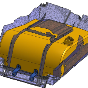
Re: Troubleshooting procedure for fillet failure (and any other failed feature, for that matter)
First images are the inside area opposite the circled area on the outside. What I noticed was that the section that should have been straight was broken up into two segments so I zoomed in and did a section (along the right plane).

The view is min radius with limits set to 9 and 11, i.e. either side of the thickness.
One way to fix it is to delete the offending faces and patch with "fill". In this case it seems to be just the vertical face, just needs a new straight edge at the bottom (using a 3d fit spline) and it works:


New Feature: Poly-Mate Connectors
My drafting team have run into situations where they've needed to define multiple explicit mate connectors in one operation for ease of organization and later reference in features. Naturally after searching for an existing tool that does multiple connectors in one operation and not finding one they requested that I develop a quality of life script that does this multi mate connector operation.
Introducing: Multi-Mate Connectors wait that's taken
Introducing: Poly-Mate Connectors

It places multiple explicit mate connectors in one go, so if you need to re-reference them multiple times it's easy to hide and show them all at once by changing the visibility of the feature itself. This makes it simple to drag select the whole window to grab all the explicit mate connectors in frame to quick select locations for hole operations or things not easily defined by sketch geometry.

New API limits = 85 requests per day per company
Why are the new limits so low? (20,000 per year per company)
And why only for private apps?
(And being only for private apps makes it look it isn't about infrastructure)
This will be terrible for exporting (~15 requests per drawing per revision once you take into account polling and getting properties and downloading the resulting file etc)
GitHub gives 120,000 per day
Google Docs gives ~85,000 per day per user
Microsoft gives 40,000 per day per company
Gitlab gives ~8500 per day per user
Onshape gives 85 per day per company
@billy2 @MichaelPascoe @Caden_Armstrong this will probably affect you