Welcome to the Onshape forum! Ask questions and join in the discussions about everything Onshape.
First time visiting? Here are some places to start:- Looking for a certain topic? Check out the categories filter or use Search (upper right).
- Need support? Ask a question to our Community Support category.
- Please submit support tickets for bugs but you can request improvements in the Product Feedback category.
- Be respectful, on topic and if you see a problem, Flag it.
If you would like to contact our Community Manager personally, feel free to send a private message or an email.
Best Of
Merchandise store
Hey All,
With onshape being so good, and engineering related merch being all the rage at the moment, I thought that it could be cool to make a Merch store?
The marketting team was at an event and were handing out hats with the logo on it - I've since lost it (I have a feeling a jealous friend stole it).
It was the best fitting hat :((((((((((((((((((

See evidence above.
Re: New Custom Feature: EZ Wire
Update the linked doc one more time. Major improvements today.
manips are much more responsive.
manips reset when you remove the pick from the blue box.
can choose bspline or polyline per bridge
cleaned up UI.

Re: Improvements to Onshape - August 29th, 2025
Thank you for the DXF update! I had just logged a support ticket on that recently!! Now if only it did not export two profiles for each hole when using the hole tool on sheet metal, will be submitting a ticket on that shortly
 Matthew
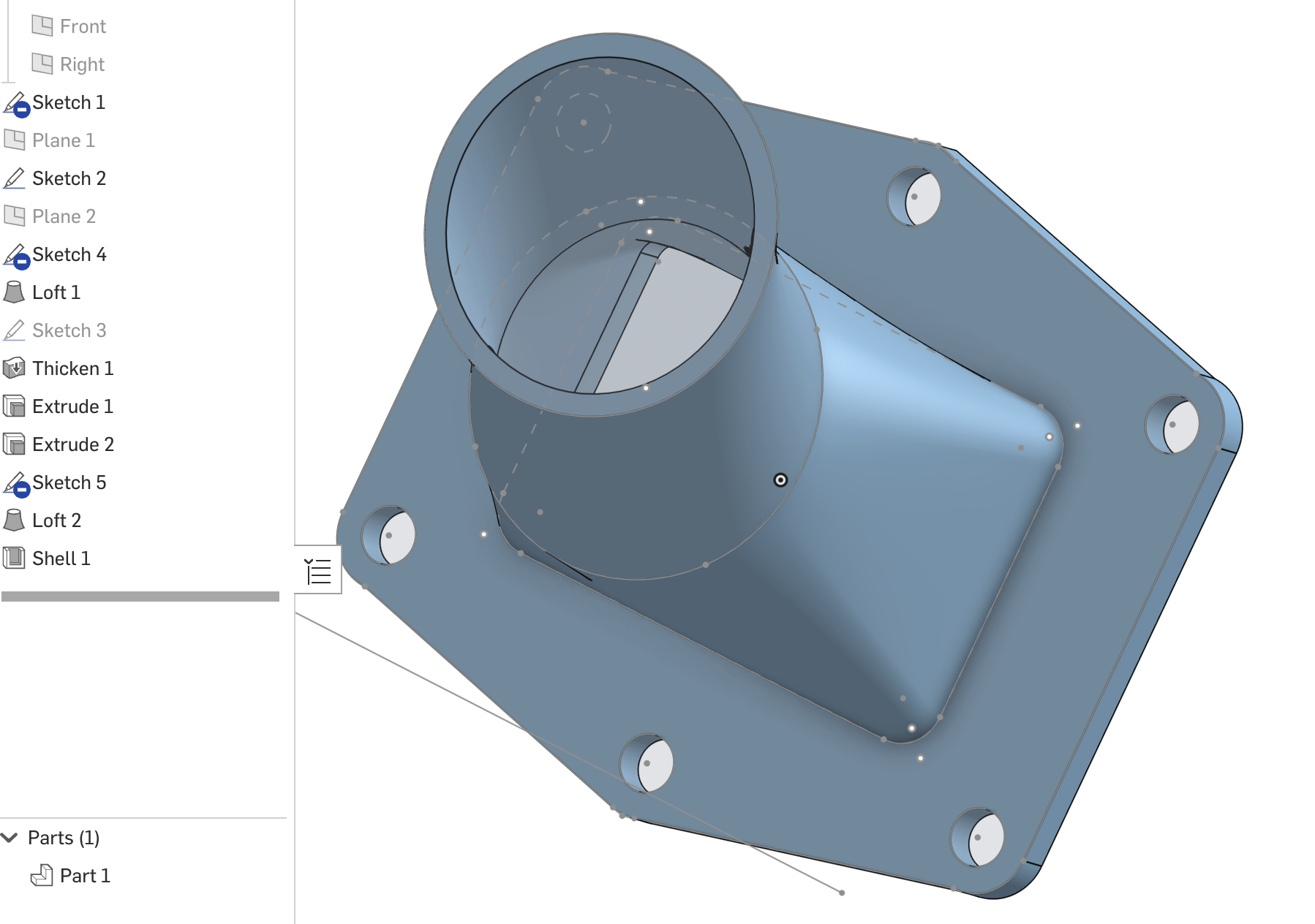
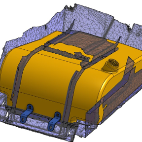
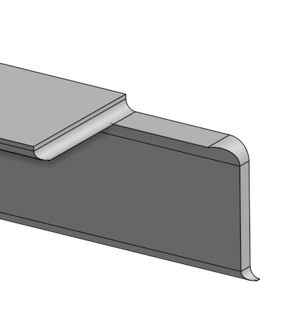
Re: how to connect these properly
Hard to know what exactly you're going for, but if my guess is right, you should do the Shell last.

Re: Linear Pattern: specify direction with xyz coordinates
Can you share an example of what your trying to do? Methods and ideas might be different depending on what the goal is
 MDesign
Frames cut list items too long
Hi,
when using the frames tool using angle steel I get funny results in the cut list when using limit frame ends.
The little extension from the subtraction of the two profiles leaves the cut list pretty much useless.
Is anyone else having trouble with this?
Tinus
Re: I don't see the new "query variable" feature in existing documents
For a kick start of the update version of a document is to send the document to trash then restore from trash. The next time the document is opened a query will ask about scheduling an update. Your answer will be 'now'. You will have to wait while the update is done.

Re: I don't see the new "query variable" feature in existing documents
Hi @ben_davis982. The bottom of every "Improvements to Onshape" post has this:
Remember:
The updates listed here are now live for all users when creating new Documents. Over the next few days, these features will also be available in Documents created before this update.

Re: PLEASE explain "externally disambiguated" / "transient" / "robust" / "tracked" / "unstable" ID's etc
@christopher_dziuba Have you seen these videos from @Alex_Kempen? It's project-based, not focused only on fundamentals, but valuable for sure. https://www.youtube.com/@TheVenomousFire /videos
