Welcome to the Onshape forum! Ask questions and join in the discussions about everything Onshape.
First time visiting? Here are some places to start:- Looking for a certain topic? Check out the categories filter or use Search (upper right).
- Need support? Ask a question to our Community Support category.
- Please submit support tickets for bugs but you can request improvements in the Product Feedback category.
- Be respectful, on topic and if you see a problem, Flag it.
If you would like to contact our Community Manager personally, feel free to send a private message or an email.
Mate : impact of the order of mate connector selection
 Math
Member Posts: 9 ✭
Hello,
I'am currently following the learning Pathway "Onshape Assemblies". I am now at the exercice "Creating Mate Connectors". And I've had difficulties with step 14.
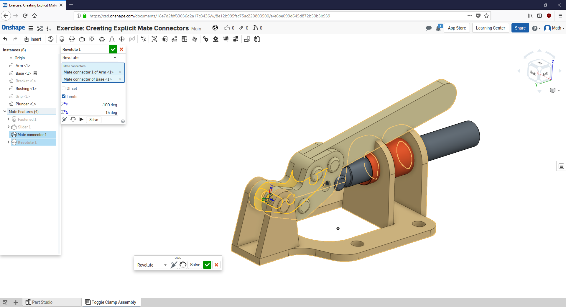
Initially, I strictly follow the steps of the text : select explicit mate connector of the arm, select explicit mate connector of the base, check the alignement of the mate and then entering the limits.
And the motion of the two parts wasn't as expected (see following picture).

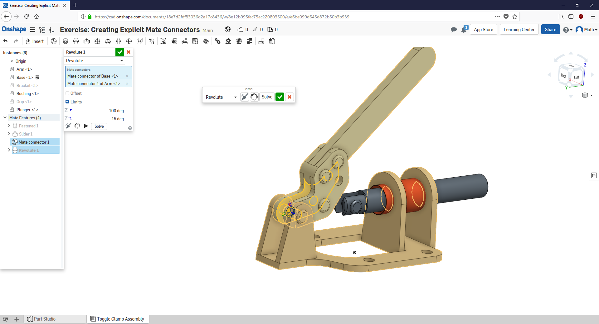
After one hour of exploring what could be wrong, I realized that on the picture of this Slide, the mate connector of base is select first and then mate connector of the arm. So I edit my mate to this order of selection.
And now, the motion of the two parts was as expected (see following picture).

So it seems that when mating two parts, the order of selection of the mate connectors has an impact on limits of the motion.
But I see nothing about this in the leaning pathway, the following technical briefing or the Onshape help :
So, there is someone could explain what happens in my case if I select the 2 mates connector in one order or the other ?
Thanks a lot !
Math
0
Best Answer
-
 john_mcclary
Member, Developers Posts: 4,043 PRO
I have noticed that behaviour once or twice before.
It would appear the first selection is treated like the main body, while the second is attached to a child.
All mates should be solved at the same time, so it shouldn't matter.
It could be a bug.5
Answers
It would appear the first selection is treated like the main body, while the second is attached to a child.
All mates should be solved at the same time, so it shouldn't matter.
It could be a bug.
One other point of confusion in the description of the revolute mate, the first mate connector selected serves as the rotational point and the second mate connector selected serves as the stationary point. It seems to me the base would be the stationary point but to make this work you have to select the base first making it the rotational point.
I am new to CAD not just OnShape so please forgive my ignorance.
Thanks
Frank
Here is an example of what is good practice for a welded assembly:
All welded brackets (selections 1) are mounted on the main frame (selection 2) for each mate. In this case, the Main frame would be fix and all brackets mate to it.
A bad practice is to mate BracketA to MainFrame + mate MainFrame to BracketB + mate MainFrame to BracketC + mate MainFrame to BracketD + etc... In this case, the frame relates to many brackets rather than many brackets relate to a single part, the frame.
When the mate has freedom (not a fastened), I always place selection 1 as the part moving relatively to the other one (selection 2). Like a linear bearing with a slider mate onto a rail. Then a carriage would be fastened on the bearing, not the bearing fastened to the carriage. This way, the carriage is mounted onto the bearing, which is mounted sliding on the rail.
In the end, you should have a "chain" of mates showing what is mounted to what, not a "web" of mates going all directions!
I hope this is clear and it helps...