Welcome to the Onshape forum! Ask questions and join in the discussions about everything Onshape.
First time visiting? Here are some places to start:- Looking for a certain topic? Check out the categories filter or use Search (upper right).
- Need support? Ask a question to our Community Support category.
- Please submit support tickets for bugs but you can request improvements in the Product Feedback category.
- Be respectful, on topic and if you see a problem, Flag it.
If you would like to contact our Community Manager personally, feel free to send a private message or an email.
Shell and draft (or a different approach) for internal support for 3D print?
 laird_broadfield
Member Posts: 42 ✭✭
Deposition printing doesn't deal well with overhangs, so there are a several different approaches to supporting overhangs sufficiently to be printed.
Most slicing tools include semiautomatic generation of fill grids or breakaway supports.
Some specialized tools are partly or all about support generation (Meshmixer shown):

And some folks just design their part so there's no unsupported overhang -- this is the approach I'm wanting to find a recipe to easily accomplish.
(I've built a test document if anybody wants to play with this: https://cad.onshape.com/documents/f76d5c67855346c2aef32402/w/5f5fb53d0c6842ca93657284.)
Let's say this is my part; simple block with filletted top edges.
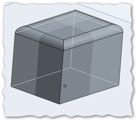
If I were making this for molding, I'd just shell it (maybe add some screw bosses and supports) then draft it.
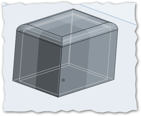
But that big roof is really hard for a deposition printer to manage.
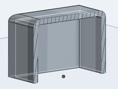
(For anybody who doesn't have direct experience, UT has a nice writeup and example pictures of things going badly here; scroll down to the "Limits of the 3D Printers" section.)
What I'm looking for is a simple recipe (just as, if I had molding in mind, shell-then-draft is pretty simple) for building support into the part. In another tab of my doc is this...
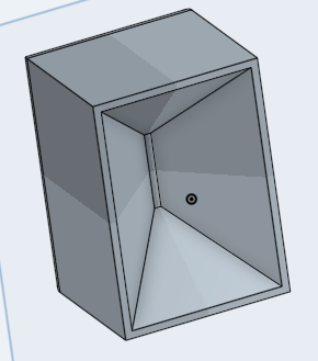
...which I created by setting the thickest shell that still left any cavity at all, then experimenting with high draft angles until I got what looked like enough support.
That process, however, is ugly and iterative, and once the part reaches real-world complexity, unworkable:
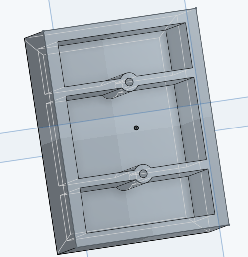
Without going all the way to a post-process with another purpose-specific tool (like Meshmixer) is there a simpler approach? Some loft approach that's not obvious to me, etc?
0
Best Answer
-
 julian_leland
Member, OS Professional, Mentor Posts: 59 PRO
@laird_broadfield: Here's what I usually do.
julian_leland
Member, OS Professional, Mentor Posts: 59 PRO
@laird_broadfield: Here's what I usually do.- Create a sketch on the surface that I'm going to have contacting the print bed (in your case, the open side of your box)
- Use the "Use" tool and other sketch tools to generate outlines for support structures. Typically, I do this by "Use"-ing all of the outer profile lines of the object being printed, offsetting them inwards by the minimum printable width that my printer supports, and then extruding them up to the object being printed. (Note to OS guys: In SolidWorks, I can save a step here by using the Thin-Extrude tool instead of offsetting & extruding. +1 for Thin-Extrude!)
- If needed, I draft one of the faces of the supports outwards, so that the face where the extrude meets the build platform is thickest. This also makes sure that the edge of the support is thin where it meets the part, making it easy to remove.
In the specific case of your box, what I'd do is draw concentric boxes inside the hollow area of the box - probably spaced around 10 mm apart - and then extrude up to the inside of the box. Good luck!6
Answers
- Create a sketch on the surface that I'm going to have contacting the print bed (in your case, the open side of your box)
- Use the "Use" tool and other sketch tools to generate outlines for support structures. Typically, I do this by "Use"-ing all of the outer profile lines of the object being printed, offsetting them inwards by the minimum printable width that my printer supports, and then extruding them up to the object being printed. (Note to OS guys: In SolidWorks, I can save a step here by using the Thin-Extrude tool instead of offsetting & extruding. +1 for Thin-Extrude!)
- If needed, I draft one of the faces of the supports outwards, so that the face where the extrude meets the build platform is thickest. This also makes sure that the edge of the support is thin where it meets the part, making it easy to remove.
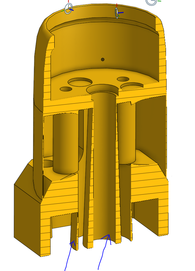
Here's an image where you can see this being done - the two things I've indicated with blue arrows are support structures that I've added in.In the specific case of your box, what I'd do is draw concentric boxes inside the hollow area of the box - probably spaced around 10 mm apart - and then extrude up to the inside of the box. Good luck!
That's not too bad, I suppose.
Very nice tip Julian. I design for my 3D printer all the time. I usually orient things to I don't use support, but that's a nice way to go about it.
I think It'd be a good idea to offset the support structure by one layer height. So if you print at 0.1mm layer height, you can extrude your support and leave a 0.1mm gap so the top surface will dingle there for that 0.1mm but would still be supported in a way.
In response to your first question, about using the Boolean to create an STL: Since there is no currently-available "Boolean Add + Keep Tools" option, I'd put the Boolean feature as the very last thing in your feature tree, and then roll back above it while you're doing design work. Then, when you're ready to print, roll forward past the Boolean, export the solid as a STL, and print!
Re: your second question - also interesting. I think it depends on the type of geometry that you're trying to create. If it's a simple shape - for example, a ball - either method will work. However, if it's a more complex shape - say, a coffee cup - then your first method (boolean of scaled part) may not work, depending on how the part scaling is performed. For instance, if the scaling function simulates all surfaces shrinking away an equal proportion from their walls, then your method will work fine. However, if the scaling function scales about a point (which I'm pretty sure it does), then it won't behave the way you want it to. In these situations, I'd go for splitting the part, shelling and adding, although you may occasionally run into weird geometry problems at the interface between the two shelled parts.
OS guys - I think there are two (good) feature requests here: Keep Tools addition to Boolean, and Scale Surfaces (or something like that - I don't know what the technical name for this would be)
Just to clarify (since I don't know how much 3D printing you've done), do your parts need to be hollow for design reasons - for example, you're modeling a water bottle - or are you just trying to reduce weight and save plastic?
@Julian_leland :
Unless I misunderstand you, I think your requested "Scale Surfaces" is essentially "Thicken", which Onshape already features?
Extrude a surface:
And then thicken the surface: