Welcome to the Onshape forum! Ask questions and join in the discussions about everything Onshape.
First time visiting? Here are some places to start:- Looking for a certain topic? Check out the categories filter or use Search (upper right).
- Need support? Ask a question to our Community Support category.
- Please submit support tickets for bugs but you can request improvements in the Product Feedback category.
- Be respectful, on topic and if you see a problem, Flag it.
If you would like to contact our Community Manager personally, feel free to send a private message or an email.
Visualize bend zone on sheet metal
 GlendonKuhns
Member, csevp Posts: 40 PRO
I often find that one of the main considerations when designing sheet metal parts is the minimum flange length. This is determined by the pressbrake tooling chosen to bend it. What I am proposing is a very simple and visual way for a designer to know where the edges of the tooling are.
The implementation in Onshape could be simple. An optional field to enter or select the width of the die in the sheet metal properties window would be perfect. The output would be a visual representation of the bend zone on the flat pattern view within the part studio.
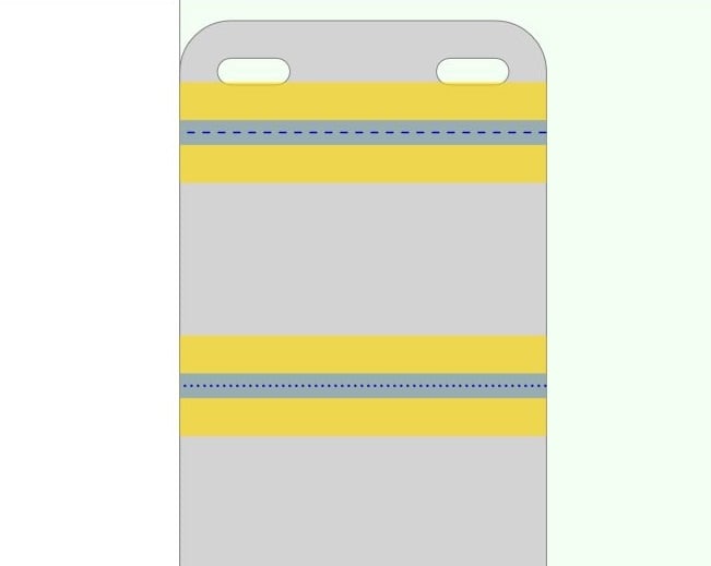
This idea comes from using Bystronic Bysoft to program parts for the pressbrake. The picture below is snipped from that software. The yellow shows the edges of the die and the blue is the bend radius area calculated from the punch selected and the thickness of the metal.

You can see from this visualization of this part that the slots should have been moved ever so slightly away from the bend line to ensure there is no improper material deformation. Also, notice that the different dashed lines denote positive/negative bends.
For comparison, here is the same part in Onshape.

7
Comments
The programming software provided by Bystronic calculates bend deductions based on the chosen punch/die combination and the material type/strength/thickness. I would absolutely love if that could all be calculated directly in Onshape, along with a dynamic/real-time cost estimator. I know that that is dreaming so that isn't my request for now.
The only thing I am requesting is to be able in Onshape to set the width of the die to make it easy to see the minimum flange length for whatever die I want to use. I have a bend chart that makes that choice easy for me and I don't need Onshape to calculate the bend deduction based on the tooling.
From a design perspective, the die width is somewhat independent from all the other inputs. I may be wrong about this for other users, but for me, this would be very valuable. Here are a couple snips from Bysoft so you can see what we see.
Different style for UP and DOWN bend lines is a brilliant idea. Thank you for bringing it up.
This request does NOT involve punches, bend radii, backgauges or fancy math.
I wish I had the time to learn FeatureScript. I doubt it would take long at all to add such a simple feature.
Twitter: @BryanLAGdesign