Welcome to the Onshape forum! Ask questions and join in the discussions about everything Onshape.
First time visiting? Here are some places to start:- Looking for a certain topic? Check out the categories filter or use Search (upper right).
- Need support? Ask a question to our Community Support category.
- Please submit support tickets for bugs but you can request improvements in the Product Feedback category.
- Be respectful, on topic and if you see a problem, Flag it.
If you would like to contact our Community Manager personally, feel free to send a private message or an email.
Sheet Metal Extrusion for Flexible Printed Circuit Boards etc
 S1mon
Member Posts: 3,795 PRO
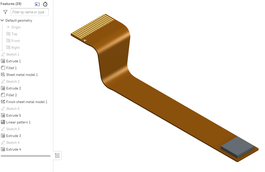
In Solidworks, whether by design or accident, it is possible to add extrusions to sheet metal parts (although it doesn't like to do this over bends). Over the years I've used this on a ton of projects to simulate flexible printed circuits. Sometimes it's a super low profile extrusion to show where contacts or silkscreen pin 1 indicators are, sometimes it simulates surface mount components.
I'm sure there are other uses for such functionality, such as welded-on features for real sheet metal parts.
I can add other parts to a part studio with a sheet metal part, but they don't show up in the sheet metal view. I can't add extrusions to a sheet metal part.
I can add features after the "finish sheet metal" feature, but they don't unfold and show in the flat pattern.
This is another one of the many things that I'm used to doing in Solidworks which would prevent me from switching.
Here's an image of an example:


Simon Gatrall | Product Development Specialist | Open For Work
Tagged:
3
Comments
Other related requests:
https://forum.onshape.com/discussion/13915/generalized-sheet-material-tools
https://forum.onshape.com/discussion/13185/sheet-metal-partial-cuts
https://forum.onshape.com/discussion/7312/countersunk-holes-in-the-sheet-metal-flat-pattern
Simon Gatrall | Product Development Specialist | Open For Work
That's cool to see, but it's doing the opposite of what I'm looking for. I want to design the bent up flex cable in 3D with components and very short extrudes for contacts and silkscreen and then be able to flatten it. The contacts and silkscreen are super helpful for making sure that pin 1 ends up in the right places, etc. I pretty much never want to design the flat pattern first and then bend up sheet metal or flex circuits. It's fantastic to be able to add details in the flattened state, but most of the design intent comes in the 3D for me.
I'm not super concerned with K-factors like in sheetmetal, since the bends are usually designed with clearance for tolerance reasons, but it would be smart to include some sort of K-factor allowances.
Simon Gatrall | Product Development Specialist | Open For Work
Part of what I'm showing in my very simple example image is a tapered section of the flex which crosses the bends. This is really hard to do if it's modeled only in 3D and unbent. There are other features like bend reliefs or curved sections which are easy to do in the flat pattern, but hard to do in 3D if they cross a bend. Conversely, modeling everything flat and then bending it at the end makes it hard to get all the geometry in the right place.
Simon Gatrall | Product Development Specialist | Open For Work