Welcome to the Onshape forum! Ask questions and join in the discussions about everything Onshape.
First time visiting? Here are some places to start:- Looking for a certain topic? Check out the categories filter or use Search (upper right).
- Need support? Ask a question to our Community Support category.
- Please submit support tickets for bugs but you can request improvements in the Product Feedback category.
- Be respectful, on topic and if you see a problem, Flag it.
If you would like to contact our Community Manager personally, feel free to send a private message or an email.
Mate Connectors
 billy2
Member, OS Professional, Mentor, Developers, User Group Leader Posts: 2,119 PRO
billy2
Member, OS Professional, Mentor, Developers, User Group Leader Posts: 2,119 PRO
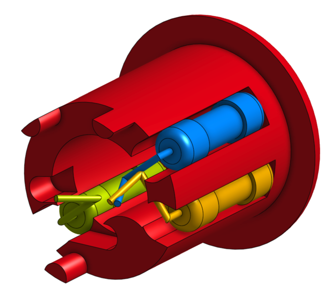
After watching the series on Mate Connectors I thought I'd give them a try. I'm not a fan of assemblies, but if you can't beat'm, join'm.
One thing to note that isn't obvious is that duplicating a part studio and copying a part studio in an assembly produces 2 different results:
-duplicating a part studio creates an independent instance of the part studio
-copying a part studio inside an assembly creates a dependent instance of the part studio
Since I need these resistors to behave independently from each other I used the duplicate part studio method. I haven't read the manual in a few weeks and I haven't read any discussions about this dependent/independent issue so maybe I'm all wrong.
So there is a bitch coming.
Since I can't currently hide part mate connectors in the assembly. I attempted to remove them from my assembly and switched to assembly mate connectors which can be hidden. I think most people will opt for assy mate connectors but I'm thinking when I create something meaningful in OS I'll create all my mate connectors in each part and then use these part mate connectors to assemble. I'm not sure if this will be better than the old style mathematics for creating assemblies. I guess we'll see....
My bitch is that assembly mate connectors don't allow moves which is very limiting rendering their effectiveness close to useless.
So you can see that with assembly mate connectors you can have a coincident and 4 rotational positions. This is too limiting and ruins this type of mating.
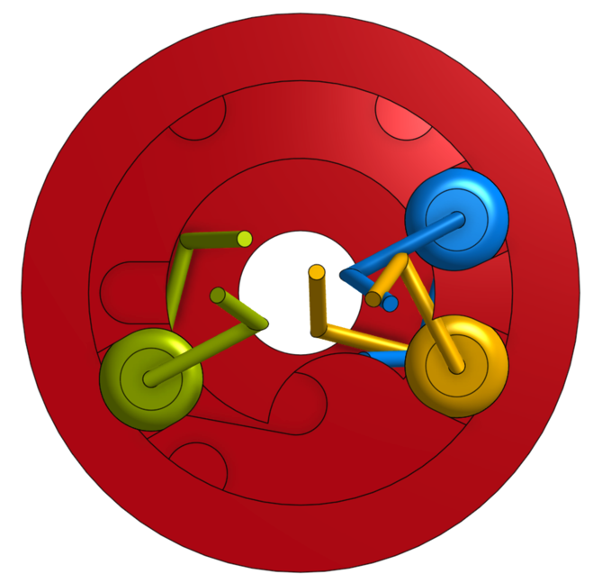
At the heart of this problem is the assembly mate connector constructs. Notice that all assembly mate connectors have the same orientations meaning they're being crossed with the root coordinates (mate connectors are coordinates and coordinates are triple products). This can't be made better so give me some corrective means.

Please give me 1 translation along the primary (Z-blue) and 1 rotation about the primary (Z-blue). The other translations and rotations are mind boggling and I don't really care about them. No one will every use these because they're too hard to comprehend. Translate x,y and rotate x,y are beyond most engineers comprehension and should be reserved for computer scientist and CAD geeks. Maybe this should be voted on. Maybe you should show the obvious primary translation & rotation and then have an advanced button that shows the others. Alright, sorry, it's not billy CAD, but exposing obvious functions and hiding more obscure stuff I believe is a good UI.

I really want the primary translation & rotation and feel this is a severe limitation. Forcing me to to do this in a part file just isn't right. When I'm designing, these adjustments will be made in the assembly not the part so please give me these.
Tagged:
0