Welcome to the Onshape forum! Ask questions and join in the discussions about everything Onshape.
First time visiting? Here are some places to start:- Looking for a certain topic? Check out the categories filter or use Search (upper right).
- Need support? Ask a question to our Community Support category.
- Please submit support tickets for bugs but you can request improvements in the Product Feedback category.
- Be respectful, on topic and if you see a problem, Flag it.
If you would like to contact our Community Manager personally, feel free to send a private message or an email.
How to design a plastic part that has been "stamped" or "pushed in"?
 Jin
Member Posts: 8 ✭
Hi,
I am not sure if I am using the right
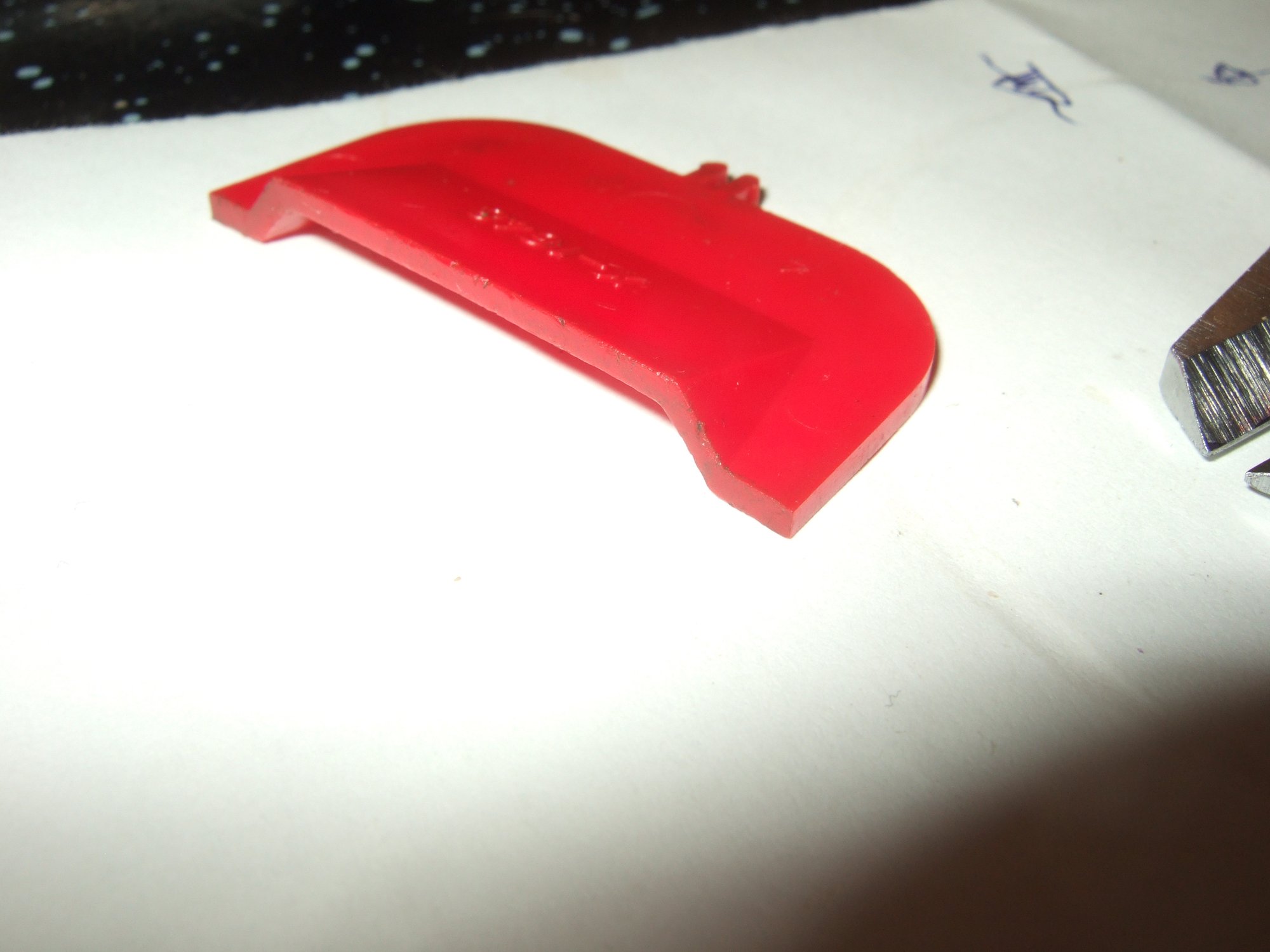
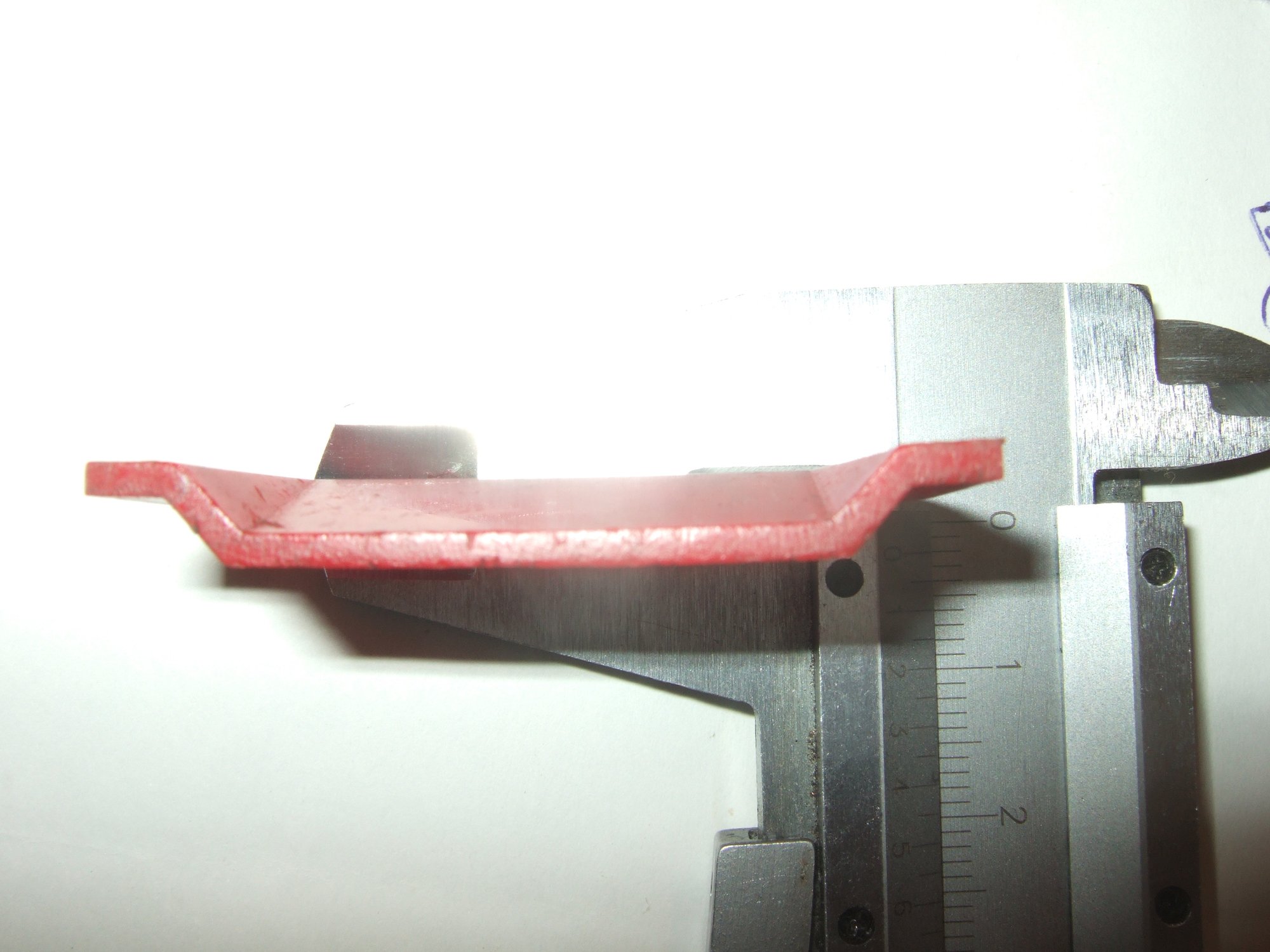
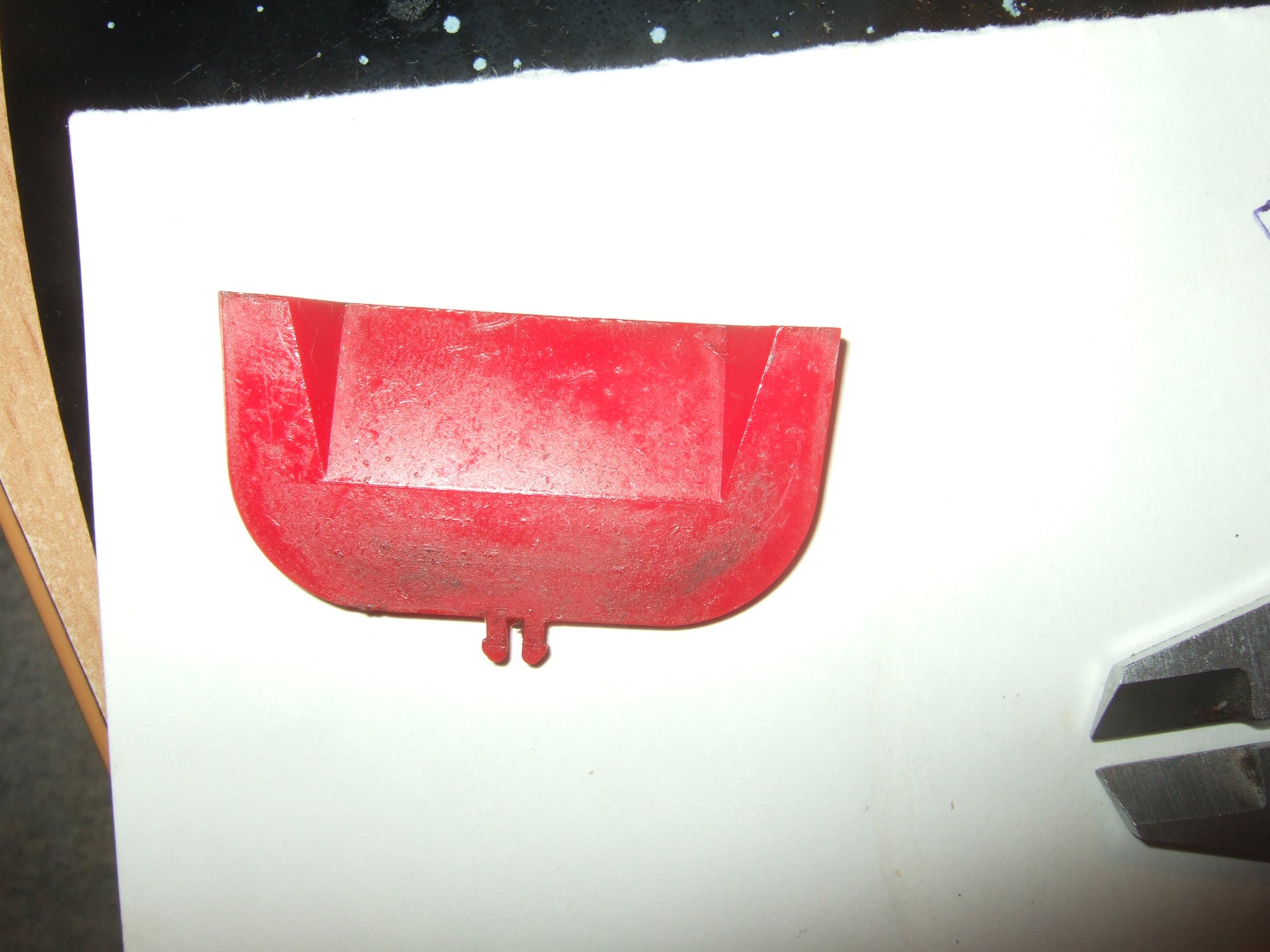
terms here when I refer to "stamping", here is the original part that I
am trying to reproduce (so that I can print a replacement for the
broken one):


I
tried several ways of doing it, but did not like any of them; my
difficulty seems to be the way of how to "push in the plastic" like in
the original part. I first tried to achieve this effect by extruding the
inner part and then applying a chamfer. It kind of looked OKish
optically from the top (top being the side that raises up), but
controlling the dimensions via chamfer angle and distance was more of a
guess-game, so clearly there must be a better way and chamfering is
probably not it.
I also failed at getting
the bottom side (the one that is pushed in) right. My attempts included
offset planes, remove-extrusions and all sorts of Extrude add/remove
combinations, but even the ones that more or less resembled the object
correctly appeared hacked up and ugly in terms of proper modelling,
which tells me that I am going about it the wrong way.
I
removed my ugly hacks, but left the attempts with the chamfered top
(which I am not happy with because the angles are not correct) so that
you can see what I mean:
Is
it somehow possible to take the "main shape extruded" solid and just
"push it in" into the chosen direction to simulate the effect of how
that part has been manufactured?
What would be the "correct" or "better" way to model something like that?
Kind regards,
Jin
0
Comments
https://cad.onshape.com/documents/90f372635b2b1109a6ecbe60/v/c21048fe022532c632f01f9c/e/884627bef50295285c4c9d20
Also, it can be very helpful to import the photos you are working with into sketches to use as a reference.
Hope this helps!
@alnis is my personal account. @alnis_ptc is my official PTC account.
Also, I just remembered: if you're adding plastic snap hooks on the model, I like to use the snap hook custom feature to keep everything neat and to make modifying the hooks later easier:
https://cad.onshape.com/documents/90f372635b2b1109a6ecbe60/v/7f90896de228605a8de726e7/e/884627bef50295285c4c9d20
I also like to print the sub-section of the model with the hooks first to test that they won't snap off. To do that, you can add a sketch with a rectangle encompassing the hooks and a little bit of the surrounding material, then extruding with the "intersect" option. That way, if the hooks break off or otherwise don't work, it's easier to iterate and get them working without using up a lot of print material and time. Just make sure to print it in the same orientation as it will be printed in the final model since 3D prints are not uniformly strong/weak in each direction.
@alnis is my personal account. @alnis_ptc is my official PTC account.
https://cad.onshape.com/documents/f8e913bca2d3889d1581ec33/w/a41755fb84c66df85d0045ae/e/bc4115550abc00ccffaf3a6b
@Jin, I think that you'll find that there are many ways to model any one part, and depending on what you have to model and what the design intent is, different tools will be best. One thing to be careful of is that you will get slightly different results from lofting a solid between profiles and lofting a surface and then thickening. Here is a document showing this (it's not too important in most cases, it's just something to keep in mind):
https://cad.onshape.com/documents/4e169a67b28e7d98e5df2198/v/c9721b8159d42fe9d0e460ab/e/5c72b194f3ca1130985515d3
The slightly thicker one (made by thickening a surface) has a thickness of 20 mm exactly, but the vertical edges of the end faces are longer than 20 mm. The slightly thinner one (made by lofting a solid between profiles) has a thickness of slightly less than 20 mm, but the vertical edges of the end faces are exactly 20 mm.
@alnis is my personal account. @alnis_ptc is my official PTC account.