Welcome to the Onshape forum! Ask questions and join in the discussions about everything Onshape.

First time visiting? Here are some places to start:
  1. Looking for a certain topic? Check out the categories filter or use Search (upper right).
  2. Need support? Ask a question to our Community Support category.
  3. Please submit support tickets for bugs but you can request improvements in the Product Feedback category.
  4. Be respectful, on topic and if you see a problem, Flag it.

If you would like to contact our Community Manager personally, feel free to send a private message or an email.

Sheet Metal Move Face

kent_hendersonkent_henderson Member Posts: 69 PRO
https://cad.onshape.com/documents/04c87755529dcde47d445aa1/w/04c2368ea7c2118167ab6eae/e/9de12eea9092b4c2a30c3d43

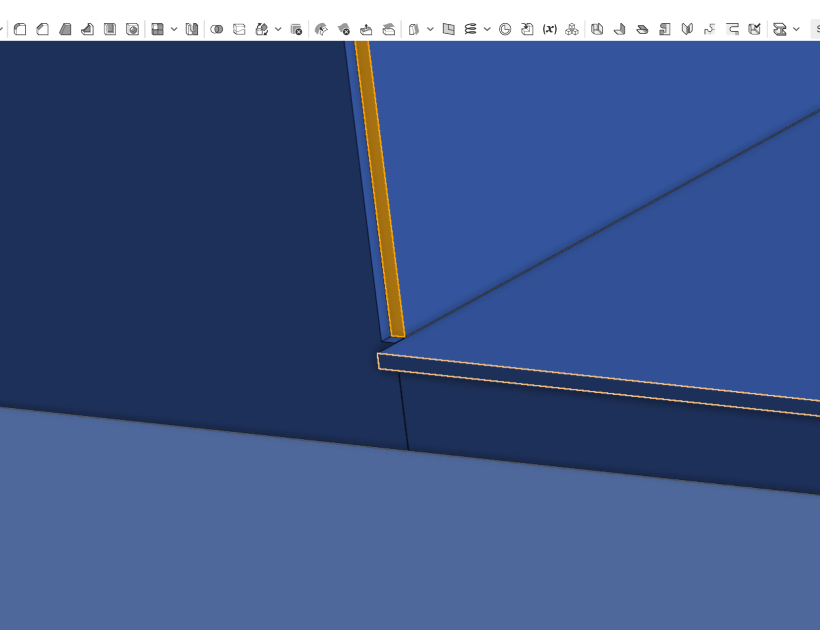
I'm struggling with moving a sheet metal face/edge. Look at the last two features in the feature tree. I need to pull all three of the sheet metal edges into the box. I can only pull one. Can anyone tell me why I can't move the other two? I moved the silhouetted face .75 but can't move the orange face the same amount. Maddening at this point......

Tagged:

Comments

  • john_mcclaryjohn_mcclary Member, Developers Posts: 3,938 PRO
    sheet-metal bodies should only be created if you want to bend or curve something and flatten out later

    Once a part is sheet-metal, it gains a lot of restrictions that prevent you from making impossible sheet-metal parts.

    Because you made everything sheet-metal from a single feature, it is treating it like a single piece of sheet-metal and is trying to make sure the corners have reliefs.

    I would recommend not using sheet-metal for this part, because they are all flat pieces, with the exception of the curved ends. You could make those Sheet-metal. 
  • kent_hendersonkent_henderson Member Posts: 69 PRO
    Thank you for your comments. Your answer may be an honest one but not the one I was looking for. SM does a lot more for me than unroll a curve. How all the edges come together on a sheet metal part are hugely important from manufacturing standpoint. This part was done as a sheet metal part because it's sheet metal. All the corner details are correct and trimmed correctly for perfect flat patterns. It's why we use Onshape.

    If this was done with extruded faces, it would require considerable time to move/trim each edge for proper fitment. Something Onshape's sheet metal does automatically, neatly, and correctly.


  • PrachiPrachi Member, OS Professional Posts: 262 ✭✭✭
    edited November 2020
    John is correct. In trying to use one sheet metal feature you have placed restrictions on where faces can be moved. I also noted that the flat pattern is broken up kind of strangely and treated as a single item that would need patching together later. In this sample there are no treatments to bring edges together but I can move the face you indicated because it is done with separate parts.
    https://cad.onshape.com/documents/bb8b8777c1b274bb25c0d4fd/w/5d55c34292bf0ef965cd271f/e/82933f2f186dc72191589388

  • matthew_stacymatthew_stacy Member Posts: 487 PRO
    @kent_henderson, I present a slightly different design approach for your consideration.  I started with the intent of creating TWO sheet metal parts, rather that the 11 individual flat pieces in you model.  But you could split my two part into  2 ≤ n ≤ 11 for convenience of fabrication.

    To me this looks like a 'chamber' and a 'duct', so that's how I modeled it.  MOVE FACE should work just fine on this new model, but that may not be necessary.  I added flanges to mount duct to chamber.

    I don't know if this approach meets your needs, but I offer it for consideration:


  • kent_hendersonkent_henderson Member Posts: 69 PRO
    Thanks Matt & Glen. The part is broken up to accommodate nesting the parts onto commercially available sheet sizes. Matt your idea of breaking this into two SM parts does solve the problem. Normally the flange would work on the take off, but I actually need it to extend into the rounded box 1/2" to create a boarder for ceramic tile lining. That's what was throwing me. By modeling the the weldment in two SM parts instead of one, I was able to move that face. Thanks again to both of you.
  • matthew_stacymatthew_stacy Member Posts: 487 PRO
    @kent_henderson, also consider alternatives to MOVE FACE for getting overlap between the duct and the rounded box.  If you're determined to do that in the Part Studio then that 'Duct' extrusion that I made could easily be extended in a second direction.

    But my first choice would probably be to provide that overlap when mating the two parts in an Assembly.
Sign In or Register to comment.