Welcome to the Onshape forum! Ask questions and join in the discussions about everything Onshape.

First time visiting? Here are some places to start:
  1. Looking for a certain topic? Check out the categories filter or use Search (upper right).
  2. Need support? Ask a question to our Community Support category.
  3. Please submit support tickets for bugs but you can request improvements in the Product Feedback category.
  4. Be respectful, on topic and if you see a problem, Flag it.

If you would like to contact our Community Manager personally, feel free to send a private message or an email.

how to make UVs more regular?

EvanReeseEvanReese Member, Mentor Posts: 2,197 ✭✭✭✭✭
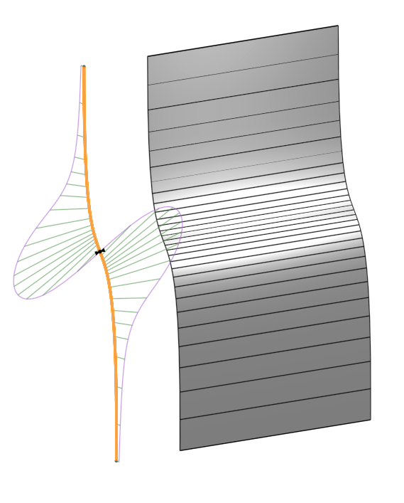
If I sketch a spline like this, and extrude it, why are the U curves all bunched up toward the middle and spaced out at the ends? It seems to correspond to the curvature graph so I guess it has something to do with the minimum level of detail needed to create the level of curvature at each point. Any ideas how I might get a more regular grid of UVs on here? For those who know me, you may have guessed this is about the Attractor Pattern feature.

Evan Reese

Answers

  • S1monS1mon Member Posts: 3,069 PRO
    Curves and surfaces are parameterized based on the spacing of the CVs. If you could show the control points of the base spline, you would see that the lengths of the control polygon in the middle are shorter than the ends, or at least the first and last control polygon lengths are too long compared to those in the middle.

    This is about Alias, but it applies to any CAD system which uses Beziers and/or B-Splines.
    https://knowledge.autodesk.com/support/alias-products/getting-started/caas/CloudHelp/cloudhelp/2019/ENU/Alias-Tutorials/files/GUID-A23E9E8C-6D6B-41AD-A0AB-3E98183FBC2E-htm.html

    Also if you play with this part of this amazing tutorial, you can see the concept of parameterization based on the number of line segments used to approximate a bezier:
    https://pomax.github.io/bezierinfo/#flattening

    Using that tool you can see how things get bunched up in the middle if the lengths of the ends of the control polygon are too long.

  • konstantin_shiriazdanovkonstantin_shiriazdanov Member Posts: 1,221 ✭✭✭✭✭
    edited January 2021
    If it always be that rectangular faces you can take one of bounding edges, evaluate point on it using evEdgeTangentLine() with arc length parametrization, then evaluate underlying surface parameter using evDistance() from between those point and the face.
  • EvanReeseEvanReese Member, Mentor Posts: 2,197 ✭✭✭✭✭
    S1mon said:
    Curves and surfaces are parameterized based on the spacing of the CVs. If you could show the control points of the base spline, you would see that the lengths of the control polygon in the middle are shorter than the ends, or at least the first and last control polygon lengths are too long compared to those in the middle.

    This is about Alias, but it applies to any CAD system which uses Beziers and/or B-Splines.
    https://knowledge.autodesk.com/support/alias-products/getting-started/caas/CloudHelp/cloudhelp/2019/ENU/Alias-Tutorials/files/GUID-A23E9E8C-6D6B-41AD-A0AB-3E98183FBC2E-htm.html

    Also if you play with this part of this amazing tutorial, you can see the concept of parameterization based on the number of line segments used to approximate a bezier:
    https://pomax.github.io/bezierinfo/#flattening

    Using that tool you can see how things get bunched up in the middle if the lengths of the ends of the control polygon are too long.

    Holy crap that's an awesome link! Thanks for sharing. Moving all of the sliders and seeing the change was so cool I found myself making disgusted faces.
    Evan Reese
  • EvanReeseEvanReese Member, Mentor Posts: 2,197 ✭✭✭✭✭
    If it always be that rectangular faces you can take one of bounding edges, evaluate point on it using evEdgeTangentLine() with arc length parametrization, then evaluate underlying surface parameter using evDistance() from between those point and the face.
    I see, is this similar to how the curve pattern handles it?
    Evan Reese
  • EvanReeseEvanReese Member, Mentor Posts: 2,197 ✭✭✭✭✭
    I found a workaround that should at least work in my case. I just made the spline with lots of points and it makes it more regular. On the right is a standard spline, and the left is my rebuilt spline. For an existing, trimmed, compound surface, I'm not sure how I'd handle it. I'll cross that bridge when I get there. Here's the link to the model below for the curious.

    Evan Reese
  • konstantin_shiriazdanovkonstantin_shiriazdanov Member Posts: 1,221 ✭✭✭✭✭
    I see, is this similar to how the curve pattern handles it?
    Curve pattern definetely uses length-proportional parametrization of selected path

  • lanalana Onshape Employees Posts: 716
    @Evan_Reese
    A word of warning, If you use more interpolation points you get "heavier" curves and surfaces both in terms of memory use and in terms of performance.
  • EvanReeseEvanReese Member, Mentor Posts: 2,197 ✭✭✭✭✭
    lana said:
    @Evan_Reese
    A word of warning, If you use more interpolation points you get "heavier" curves and surfaces both in terms of memory use and in terms of performance.
    Thanks for the warning. I'll keep it in mind.
    Evan Reese
  • steve_shubinsteve_shubin Member Posts: 1,098 ✭✭✭✭
    edited January 2021
    It seems to correspond to the curvature graph so I guess it has something to do with the minimum level of detail needed to create the level of curvature at each point. Any ideas how I might get a more regular grid of UVs on here?
    Hi Evan,
    It's obvious the below is not evenly spaced like your solution. But with less interpolation points as Lana spoke of, maybe it's something to consider at times

    Of course, this is not shaped the same as your spline. I was prioritizing the spacing between the tines, and this is what I came up with

    And, I'm liking the stuff you've been doing
    Impressive


  • EvanReeseEvanReese Member, Mentor Posts: 2,197 ✭✭✭✭✭
    @steve_shubin I think something like that is a good middle ground. I was just focused on quickly understanding and solving this problem, but I didn't give a whole lot of thought to how few points I could get away with to still get an acceptable result. I'd guess I could probably cut my point count by 1/2 or 2/3 and still end up with a similar result. The rebuild time for my example above is 304ms, which isn't too bad, and is especially when you consider that 223ms of it is the Curve Pattern I used to quickly get some regularly spaced points. I think with a carefully sketched spline (and no curve pattern) the difference in the "heaviness" of the curves and surfaces will be negligible for what I'm doing.
    Evan Reese
Sign In or Register to comment.