Welcome to the Onshape forum! Ask questions and join in the discussions about everything Onshape.
First time visiting? Here are some places to start:- Looking for a certain topic? Check out the categories filter or use Search (upper right).
- Need support? Ask a question to our Community Support category.
- Please submit support tickets for bugs but you can request improvements in the Product Feedback category.
- Be respectful, on topic and if you see a problem, Flag it.
If you would like to contact our Community Manager personally, feel free to send a private message or an email.
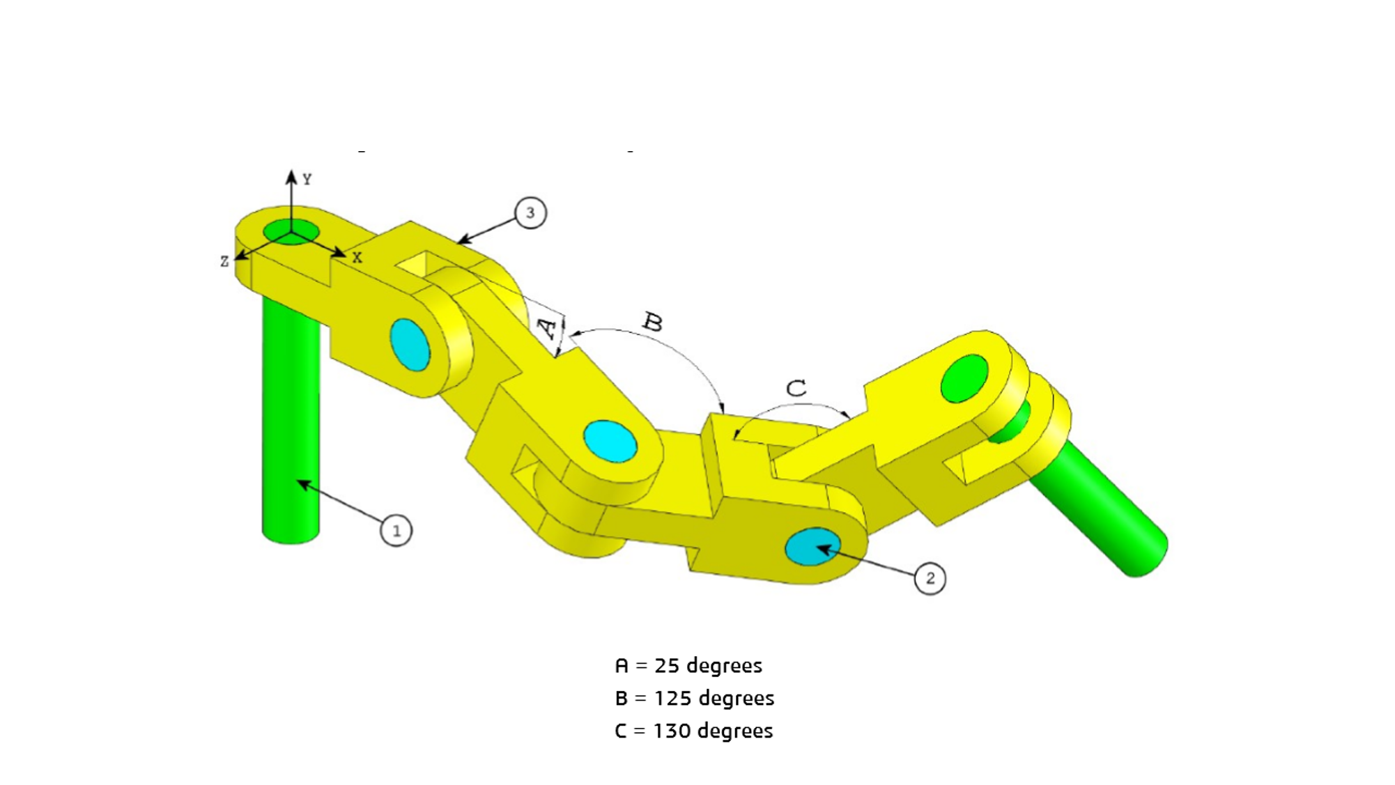
Trying to mate two parts at a specified angle in an assembly. See the chain, long pin and short pin
 Ralph_Hamilton
Member Posts: 9 EDU
Trying to mate the faces of  two parts at a specified angle in an assembly. See the chain, long pin and short pin assembly attached.
 two parts at a specified angle in an assembly. See the chain, long pin and short pin assembly attached.
 0
Best Answer
-
 billy2
Member, OS Professional, Mentor, Developers, User Group Leader Posts: 2,115 PRO
This is a classic reverse dependency problem. Onshape can compute A, B & C for you.
Typically, you'll know where the green shafts are located and want to know A, B & C angles to make this happen. Changing the location of either green shaft will update A, B & C. This is the basis of any robotics or automation exercise. Don't try to go from one green shaft to the other green shaft by typing in angles, instead, determine where the shafts are located and have onshape compute the angles.
I'd group green to yellow and cyan to yellow to simplify the solution. In the end I'd have 3 movable links and 1 fixed link.
To achieve what you want, I'd create 3 fixed mates and change the angle between the links. You'll have to edit the mate connectors to change the angle and not the mate. This is confusing the fact that you have mates & mate connectors and I've created an enhancement request to clean this up. While editing the mate, you can't change the mate connector. You have to exit the mate to edit the mate connector. This has been cleaned up in other areas of the program, but here, in an assembly, it's clunky.
What interests me, create 3 revolute mates and control where the green shafts are located. Then ask onshape for the angles that make this true. If it's not possible, then it'll error out. This gives you the ability to position a robots end effector in your assembly and ask for the angles to make this true.The base angle is 56.939° to make this true
0
Answers
Typically, you'll know where the green shafts are located and want to know A, B & C angles to make this happen. Changing the location of either green shaft will update A, B & C. This is the basis of any robotics or automation exercise. Don't try to go from one green shaft to the other green shaft by typing in angles, instead, determine where the shafts are located and have onshape compute the angles.
I'd group green to yellow and cyan to yellow to simplify the solution. In the end I'd have 3 movable links and 1 fixed link.
To achieve what you want, I'd create 3 fixed mates and change the angle between the links. You'll have to edit the mate connectors to change the angle and not the mate. This is confusing the fact that you have mates & mate connectors and I've created an enhancement request to clean this up. While editing the mate, you can't change the mate connector. You have to exit the mate to edit the mate connector. This has been cleaned up in other areas of the program, but here, in an assembly, it's clunky.
What interests me, create 3 revolute mates and control where the green shafts are located. Then ask onshape for the angles that make this true. If it's not possible, then it'll error out. This gives you the ability to position a robots end effector in your assembly and ask for the angles to make this true.
https://forum.onshape.com/discussion/10616/new-custom-feature-arrows/p1
Simon Gatrall | Product Development Specialist | Open For Work