Welcome to the Onshape forum! Ask questions and join in the discussions about everything Onshape.
First time visiting? Here are some places to start:- Looking for a certain topic? Check out the categories filter or use Search (upper right).
- Need support? Ask a question to our Community Support category.
- Please submit support tickets for bugs but you can request improvements in the Product Feedback category.
- Be respectful, on topic and if you see a problem, Flag it.
If you would like to contact our Community Manager personally, feel free to send a private message or an email.
Mirror feature does not work properly with sketches and configuration variables
 oleksandr_slovak
Member Posts: 6 ✭
Hi!
There is a very annoying issue that breaks completely our workflow.
The mirror feature in the part studio does not work properly with sketches if a configuration variable was used in a sketch geometry.
When the first time created it does its job, but once I try to change the configuration - it fails.
1. Sometimes it just mirrors the default sketch ignoring changes of the configuration variable.
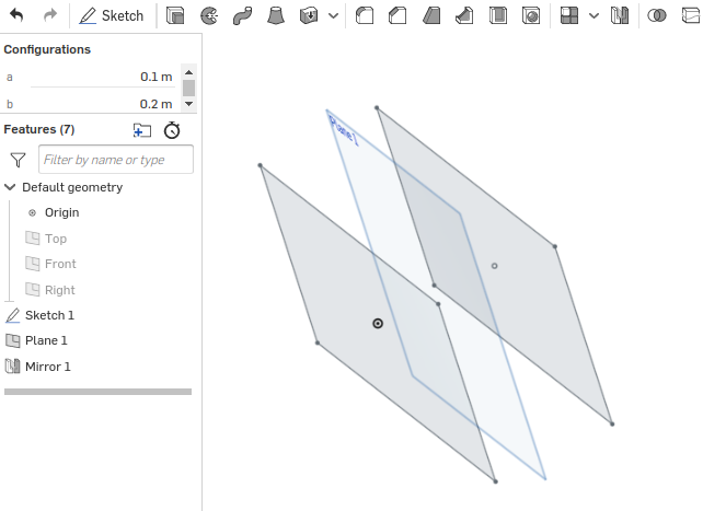
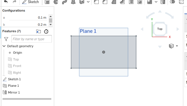
2. Sometimes it does crazy shifts like in the image below. There is a simple fully defined sketch with a center point rectangle parametrized by #a and #b. The sketch is mirrored with respect to the plane which is parallel to the sketch plane. With default config, two rectangles are the same and coincide when looking from the top.


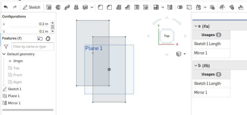
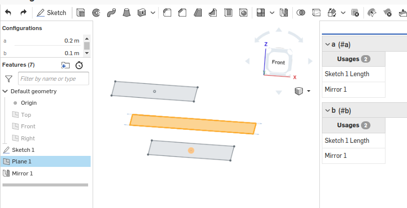
But once I change config - it starts looking like this:


Dimensions are correct (sometimes not) but the center of the mirrored sketch is placed randomly.
https://cad.onshape.com/documents/5557cd846b03bea657c7c535/w/e0a4a3a9bd81ab729eca63ff/e/e485c2a6a8f46b5983eacd3b
In both situations, mirror guaranty does not hold anymore which is unacceptable for mechanical CAD, as far as I understand. I might be wrong, please correct me in such a case.
The mirror feature in the part studio does not work properly with sketches if a configuration variable was used in a sketch geometry.
When the first time created it does its job, but once I try to change the configuration - it fails.
1. Sometimes it just mirrors the default sketch ignoring changes of the configuration variable.
2. Sometimes it does crazy shifts like in the image below. There is a simple fully defined sketch with a center point rectangle parametrized by #a and #b. The sketch is mirrored with respect to the plane which is parallel to the sketch plane. With default config, two rectangles are the same and coincide when looking from the top.


But once I change config - it starts looking like this:


Dimensions are correct (sometimes not) but the center of the mirrored sketch is placed randomly.
https://cad.onshape.com/documents/5557cd846b03bea657c7c535/w/e0a4a3a9bd81ab729eca63ff/e/e485c2a6a8f46b5983eacd3b
In both situations, mirror guaranty does not hold anymore which is unacceptable for mechanical CAD, as far as I understand. I might be wrong, please correct me in such a case.
Does anybody, except me, experience similar behavior?
Is there a way to work around it?
Many thanks!
Is there a way to work around it?
Many thanks!
Tagged:
0
Comments
The Onsherpa | Reach peak Onshape productivity
www.theonsherpa.com
It seems that in this case removing the constraint is causing the sketch to move undesirably. Could you try removing the external coincident constraint between the origin and the centerpoint of the rectangle (if you hover over the centerpoint it is the constraint that looks blue instead of grey, blue meaning "constrained to something outside the sketch") and replace it with a "fix" constraint instead?
https://cad.onshape.com/documents/0a8bce7c901ee33d26fcea8b/w/024b2f0fd3343771763a4155/e/3a49ef413d4c7243fc0922cd
I do partially agree with you, all the external constraints must be removed.
But the new, "mirror" constraint, has to be added. It perfectly and intuitively works inside the sketch by mirroring geometry with external references. You can find a simple example here. There is a circle, with external constraint (Origin) which is mirrored wrt some line. Obviously, there is no "coincide with origin" constraint at the center point of the new circle, but there is a new mirror constraint added to all three parties: circles and line.
How this example is fundamentally different from the 3d case with the plane?
>> Could you try removing the external coincident constraint between the origin and the centerpoint of the rectangle
That works, but it is obviously not practical and significantly restricts the functionality of the sketch.
Best regards,
Oleksandr Slovak
The linear pattern indeed works for some cases. You must know distance and direction.
But it does not work for the case when the mirror plane is not parallel to the sketch plane.
The surface trick does not work as it does not preserve all the geometry from the original sketch.
Best regards,
Oleksandr Slovak
I agree though it is clear that this case is not working as intended, and we are discussing a more robust solution internally.
You may be asking "Well why do you even solve the second sketch, giving it the opportunity to look different once the external constraints are removed?? We already know what it looks like, just make a mirrored copy of that!"
That's basically the gist of the solution we are discussing