Welcome to the Onshape forum! Ask questions and join in the discussions about everything Onshape.
First time visiting? Here are some places to start:- Looking for a certain topic? Check out the categories filter or use Search (upper right).
- Need support? Ask a question to our Community Support category.
- Please submit support tickets for bugs but you can request improvements in the Product Feedback category.
- Be respectful, on topic and if you see a problem, Flag it.
If you would like to contact our Community Manager personally, feel free to send a private message or an email.
Moving multi-jointed/multiply-mated assemblies (inverse kinematics in OnShape?)
 gabriel_grant
Member Posts: 8 EDU

Is there a detailed description somewhere of how OnShape handles part movement in multi-joint chained assemblies? Specifically wondering about why it seems like sometimes moving a part at the end of a chain appears to work as expected (ie pretty much how it would in the physical world, presumably using inverse kinematics calculations?) and why it sometimes seems like there is only one degree of freedom accessible.
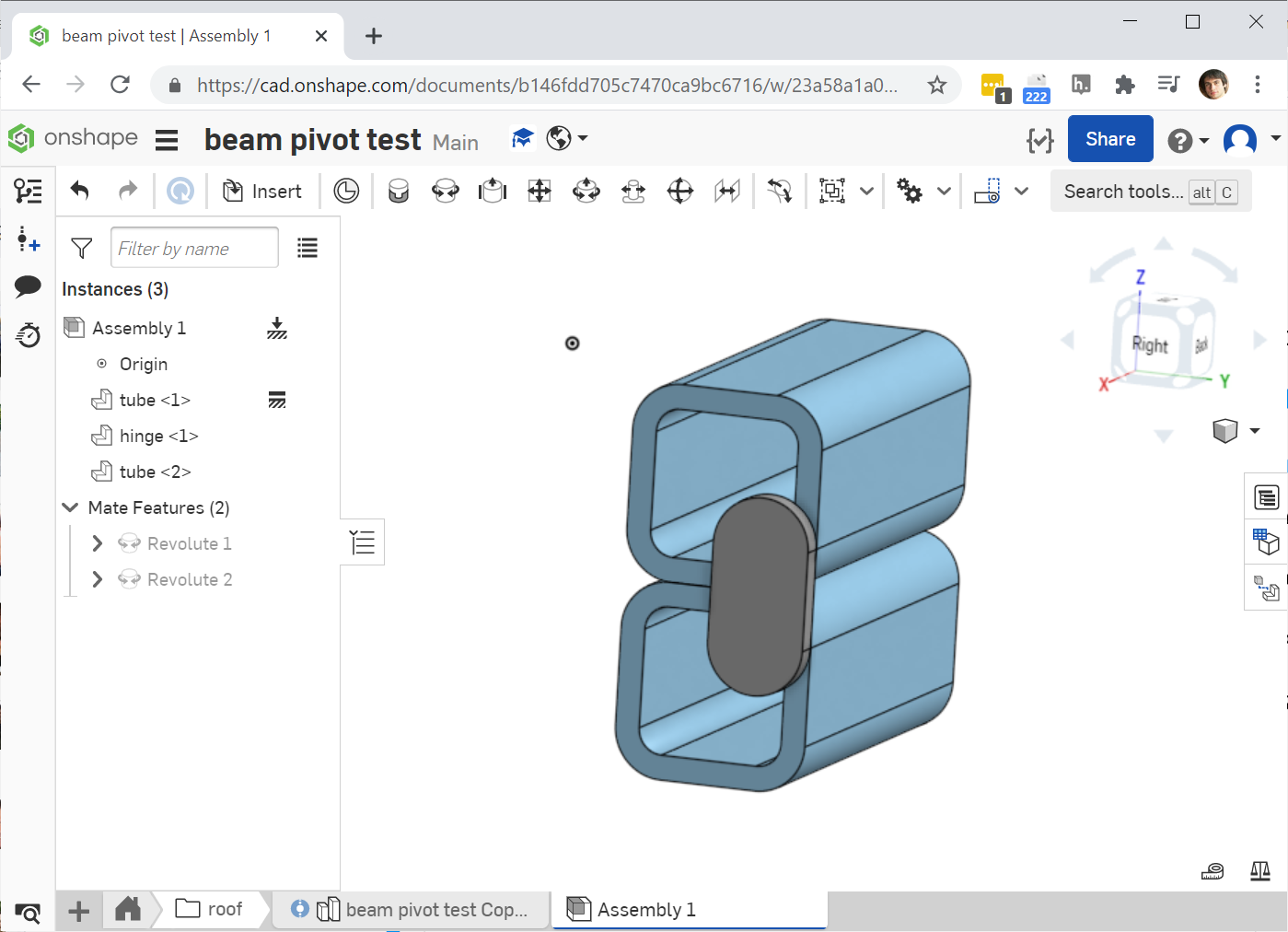
Take, for example, the following simple, multi-pivot hinge:
https://cad.onshape.com/documents/b146fdd705c7470ca9bc6716/w/23a58a1a0be0a81de8833e28/e/c4b60b712dc102e5d7fbd15d

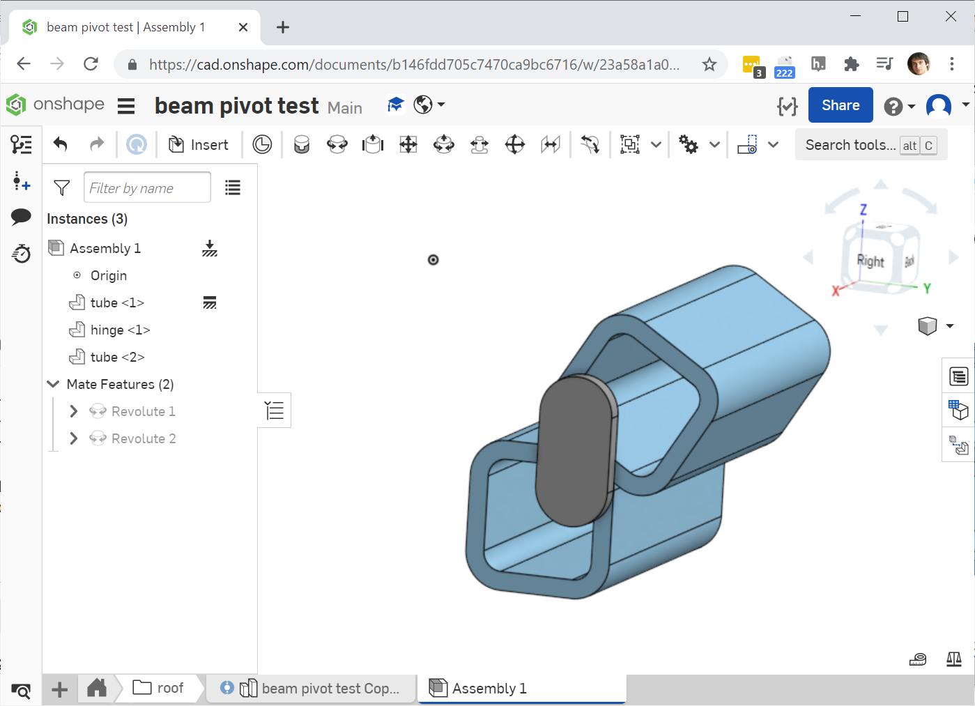
The lower section of square tube is fixed, the "hinge" piece is revolute-mated, to that lower tube section, and then the upper tube section is revolute mated to the hinge. Dragging the top tube around only seems to affect the last revolute mate (between the hinge piece and the free tube), but not the revolute mate between the fixed tube and the hinge piece, so the top piece's total movement is constrained


(mouse isn't shown, but this screenshot is taken while trying to drag the top tube up and to the right. note the hinge bar is still vertical, when in reality it would also rotate to extend the range of the upper square tube piece further up and to the right)
Of course the full range of motion can be explored by moving each of the joints individually, but for getting a sense of part movement (and especially with longer/more complex chains), it's handy to be able to just move the outermost part and have the rest follow. Is there something I can be doing differently in constructing these chains to make sure that's consistently possible?
Also, relatedly, is there a simple way to reset all mates? I find myself frequently "right-click -> Reset"-ing each one in these chains, and often resetting one will mess up another that had already been reset. Maybe just always setting a named position in the default state is the best approach?

Tagged:
0
Answers
When working with revolute mates, I've found that setting angular limits can also help make additional movement simpler since it prevents issues with over centering and the like.
Lastly, note that the order of parts and/or mates in the assembly list doesn't affect assembly behavior since mates are solved simultaneously. Also, making a named position is probably the easiest way to save the state of an assembly.
FRC Design Mentor - Team 1306 BadgerBots
In case the screenshots of the linked example doc aren't clear, I've uploaded a video of the second link remaining fixed until manually manipulated:
In your example, I think you'll be able to get the second piece to also move if you put rotational limits on your revolute mates using the limit option, then try dragging past one of the limits you've set.
FRC Design Mentor - Team 1306 BadgerBots
So it seems to me like this is just an OnShape bug, but that can be worked around by setting non-limiting rotation limits
Video showing the issue: