Welcome to the Onshape forum! Ask questions and join in the discussions about everything Onshape.

First time visiting? Here are some places to start:
  1. Looking for a certain topic? Check out the categories filter or use Search (upper right).
  2. Need support? Ask a question to our Community Support category.
  3. Please submit support tickets for bugs but you can request improvements in the Product Feedback category.
  4. Be respectful, on topic and if you see a problem, Flag it.

If you would like to contact our Community Manager personally, feel free to send a private message or an email.

Strategies for modelling injection molded parts

nick_papageorge073nick_papageorge073 Member, csevp Posts: 807 PRO
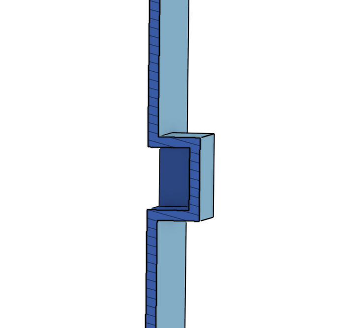
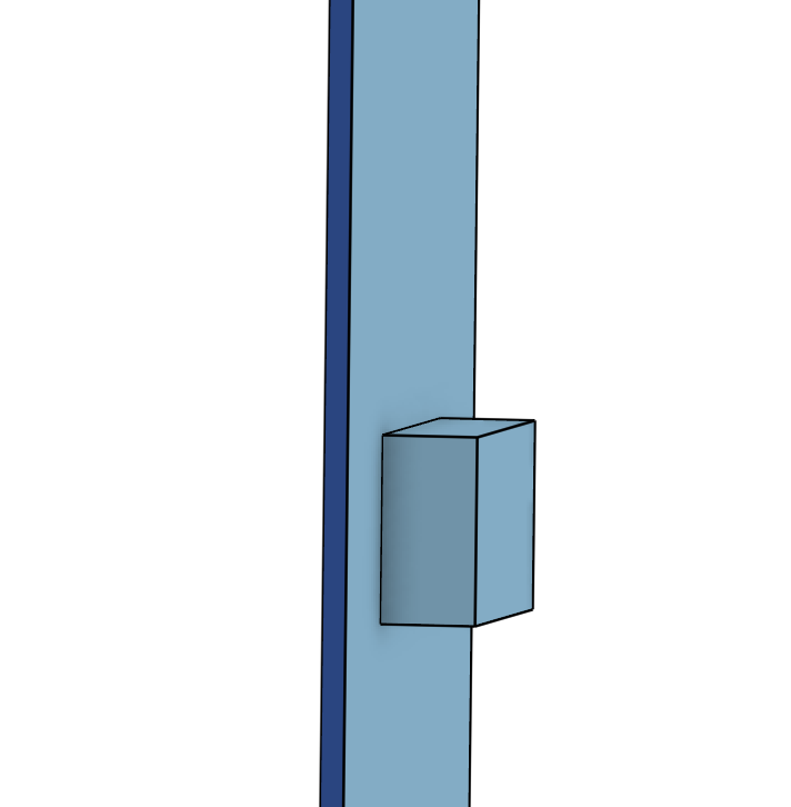
Hi all I'm having a hard time figuring out a workflow for adding features to constant wall injection molded parts. I will share a very simple example for discussion of strategy. Of course a real part the geometry would be much more complex. The example is a straight wall of an injection molded part that has a square area sticking out. Outer side of the wall is shown in the first picture. Section of wall is shown in the second picture. This is the desired shape.

I made this by drawing the wall, then drawing the box, then trimming each to each other, then boolean union the two surfaces together. Then thickening the resultant surface to the nominal wall of the part.

This works great. What I'm having trouble figuring out is how to make the same shape if the straight wall has already been thickened earlier in the tree. For example a part is far along in modelling and development, and then a feature like this square is decided to be added on. It often doesn't make sense to roll back before the main wall is thickened to add a new small feature.

Here is the public document. One workspace shows the strategy shown here called "thicken after merging" The second workspace, "thicken before square" is my attempt to make the same shape after the main wall has been thickened. I did not get all the way to the end, and it seems I have a lot of steps.

Public document:

I'd appreciate any strategies to deal with this concept! Thanks all!


Comments

  • JollyJolly Member Posts: 81 PRO
    Why the use of so many surfaces? I'm not a molder so maybe that's common. I've only really done one complicated molded part in onshape I set a thickness variable for how thick the nominal wall thickness was then just used extrudes/removes. For the example part I could see it being made with only 1 sketch and 3 extrudes (2 extrude, 1 remove). And uses a variable for wall thickness such that if you changed the variable all the walls would change appropriately.
  • nick_papageorge073nick_papageorge073 Member, csevp Posts: 807 PRO
    Jolls said:
    Why the use of so many surfaces? I'm not a molder so maybe that's common. I've only really done one complicated molded part in onshape I set a thickness variable for how thick the nominal wall thickness was then just used extrudes/removes. For the example part I could see it being made with only 1 sketch and 3 extrudes (2 extrude, 1 remove). And uses a variable for wall thickness such that if you changed the variable all the walls would change appropriately.

    Its just a simple example to illustrate the point. The real part I'm designing is this. I have the front, back, left, right, and top modeled and thickened. I am attempting to use the inner surfaces of the top to make a step on the four other pieces so the top can slide on and fit flush with the other pieces when done. Every part has draft in different directions. Every part has curves on all the surfaces. I typically model things like this with all surfaces, then thicken towards the end. But I'm new to Onshape, and trying to figure out a workflow.


  • nick_papageorge073nick_papageorge073 Member, csevp Posts: 807 PRO
    Here you can see I was able to use the inner surfaces of the top to cut away that area of the front where the top overlaps. (and would actually use an offset of the top inner surface to provide clearance). This was a lot of effort, a lot of steps, and I still don't have a way to fill it in. The public example with the flat wall and the square is the same concept. If I can figure out an efficient way to do that concept, then I can apply it to the real design. And it would have to be applied to the front/back and left/right. All 4 parts need a step for the top to slide on.


  • JollyJolly Member Posts: 81 PRO
    In my experience I'd probably still use a sketch with the inner/outer wall and the difference between them a variable (thickness). Then extrude the outer wall as a solid the make the outer surface (you'd have the square/cube). Then extrude (remove) the inner wall "up to surface" but offset by the thickness variable. Then you'd have to apply draft. Would that work? I think that's only a few steps.
  • PrachiPrachi Member, OS Professional Posts: 262 ✭✭✭
    edited March 2021
    I gotta go with Jolls.
    Looks like a lot of work to use surfaces and thicken for the sample given.
    Some draft is already included in this sample.
    Try adjusting #wall and every thing will update.
    https://cad.onshape.com/documents/44300b8443e31a8a7552cb4e/w/9ece92663a727e60560de254/e/bd0929f55e8be2408b615bb8
  • JollyJolly Member Posts: 81 PRO
    Fisher said:
    I gotta go with Jolls.
    Looks like a lot of work to use surfaces and thicken for the sample given.
    Some draft is already included in this sample.
    Try adjusting #wall and every thing will update.
    https://cad.onshape.com/documents/44300b8443e31a8a7552cb4e/w/9ece92663a727e60560de254/e/bd0929f55e8be2408b615bb8

    Nice use of shell. I like that better than my multi extrudes.
  • nick_papageorge073nick_papageorge073 Member, csevp Posts: 807 PRO
    Thanks guys. However I don't think that would work for a more complex shape. Lets say someone modelled a car shell, and then modelled the fender flare separately. Then they wanted to merge the fender to the main shape. And line up both the inner and outer walls of both. Everything is organic shaped. No straight surfaces. No extrudes used to build the organic shaped car body or fender. How would you merge the walls in that case?
  • PrachiPrachi Member, OS Professional Posts: 262 ✭✭✭
    It doesn't necessarily work for more organic shapes.
    The point is to use the simplest technique for what your working on. In the sample given solids would do the job nicely with out as much complexity.
    Use both surfaces and solids to as needed to accomplish your task.
    I personally like a shorter feature list. Parts can become quite complex and convoluted on their own with out my technique adding to that.
    https://cad.onshape.com/documents/44300b8443e31a8a7552cb4e/w/9ece92663a727e60560de254/e/bd0929f55e8be2408b615bb8
  • nick_papageorge073nick_papageorge073 Member, csevp Posts: 807 PRO
    edited March 2021
    I finished the modelling in that area. I ended up doing it like I would have in Creo. I added the features I needed to form the inset for the lid on the front/back/left/right when only the inner surface of the relevant part was modeled, before it was thickened to form a solid part with a wall thickness. Many features, all surfaces, but I don't know if there is a more efficient way of doing it.

    In Creo, another way some of my coworkers (from a prior job that was all mass produced injection molded consumer products) liked to do things like this is model one surface that represents the inner wall, and then offset it the wall thickness, to represent the outer wall. So there are two quilts (surfaces), one inner wall, one outer wall. They are not merged together yet, they stand on their own. Then, when features are added to the part, each of those features is built the same way. You model its inner surface, and offset it for its outer surface. Then the inner wall of the new feature is merged with the inner wall of the main quilt. Then the outer wall of the new feature is merged with the outer wall of the main quilt. At the very end of the tree, you merge the inner wall of the main quilt (now having all the subsequent features as part of its quilt), with the outer wall of the main quilt. This produces a lot of features in the tree, but the models are very robust. And you can add or subract features at will without much risk of regeneration failures, as long as you do them before the main merge of the inner and outer quilt.

    When I saw how easy it was to actually build in solids in Onshape instead of surfaces, I thought there might be a more efficient way of modelling injection molded parts. (this product is actually thermoformed, but the geometry principles are very similar). Doing it this way I'd say was a longer tree in Onshape than Creo. The reason is, in Creo when you merge two quilts, they trim and union automatically. In Onshape, to union two surfaces, you have to do two splits, then a union, then a delete part. 1 feature vs 5 features. Onshape has an advantage though that you can merge (union) many surfaces in one feature, whereas in Creo its only 2 quilts per merge. But I was not able to take advantage of that in this particular case the way I went about it.


  • EvanReeseEvanReese Member, Mentor Posts: 2,083 ✭✭✭✭✭
    I usually wouldn't use surfacing for this, even though I'm very comfortable with surfacing tools. Here's how I'd do it.
    1. extrude the new box to add as a solid
    2. use it to cut away the intersecting area
    3. shell the new box to your nominal wall thickness
    4. boolean both parts together

    Evan Reese
  • nick_papageorge073nick_papageorge073 Member, csevp Posts: 807 PRO
    I usually wouldn't use surfacing for this, even though I'm very comfortable with surfacing tools. Here's how I'd do it.
    1. extrude the new box to add as a solid
    2. use it to cut away the intersecting area
    3. shell the new box to your nominal wall thickness
    4. boolean both parts together

    Thank you. That looks workable for a lot of situations.

    PS, is your recording something built into onshape? Or is it a regular screen capture tool? I see a few people have similar in their posts. I'm not sure how its done.
  • PeteYodisPeteYodis Moderator, Onshape Employees Posts: 541
    @nick_papageorge073 This one is super lightweight and simple:

    https://www.cockos.com/licecap/
  • EvanReeseEvanReese Member, Mentor Posts: 2,083 ✭✭✭✭✭
    I've been using Giphy Capture, but there may be better ones out there.
    Evan Reese
Sign In or Register to comment.