Welcome to the Onshape forum! Ask questions and join in the discussions about everything Onshape.
First time visiting? Here are some places to start:- Looking for a certain topic? Check out the categories filter or use Search (upper right).
- Need support? Ask a question to our Community Support category.
- Please submit support tickets for bugs but you can request improvements in the Product Feedback category.
- Be respectful, on topic and if you see a problem, Flag it.
If you would like to contact our Community Manager personally, feel free to send a private message or an email.
Creating a surface from 3d fit lines
 brandon_furtwangler
Member Posts: 12 ✭
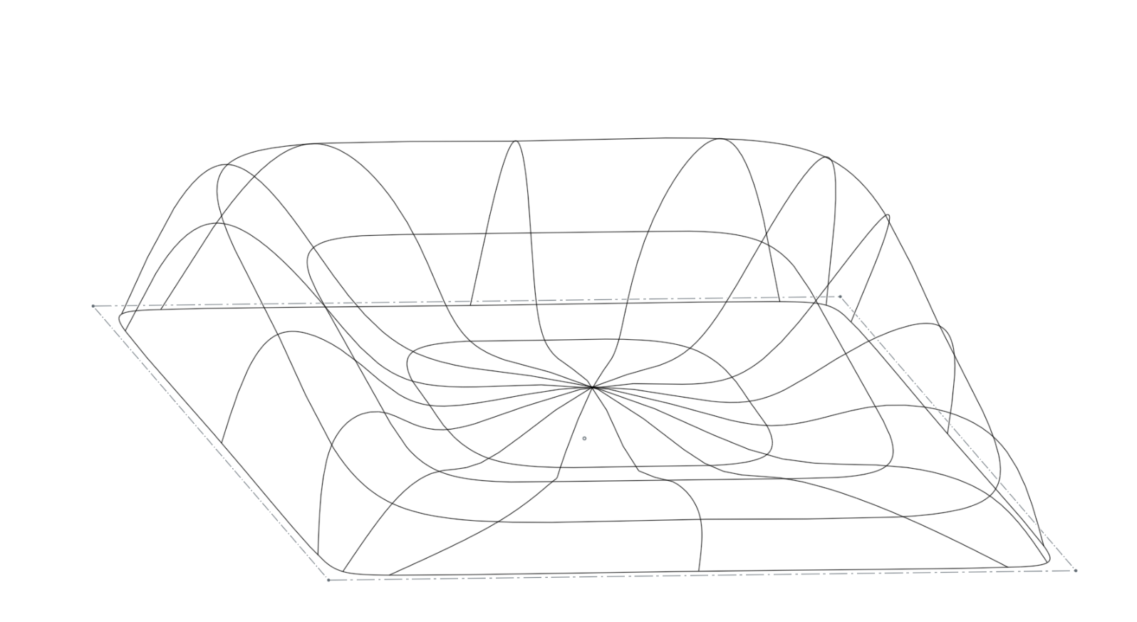
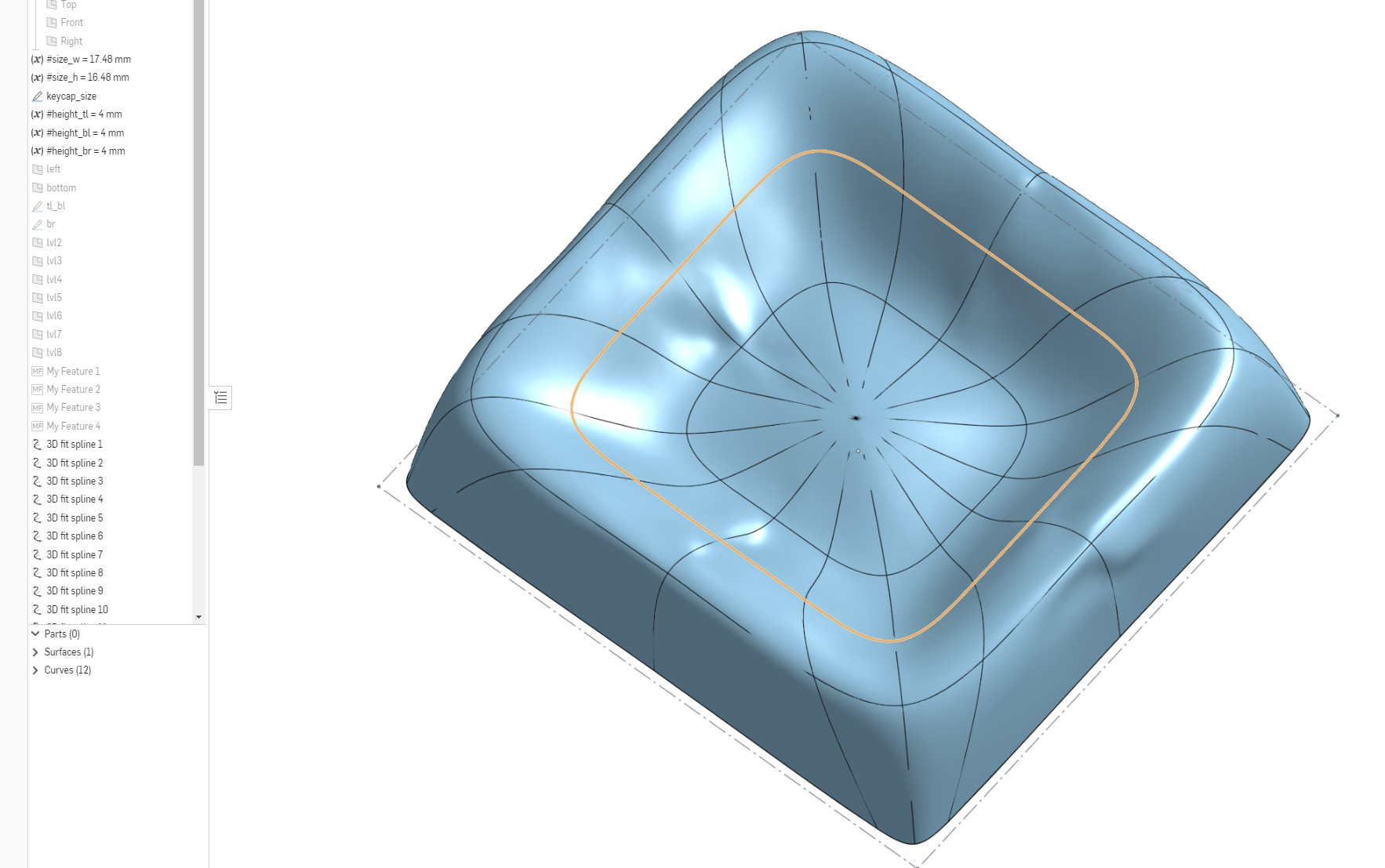
I've defined a set of contour lines using 3d fit planes to get the shape I want, and I was hoping to either fill the outside contour or use some lofting to get a nice surface that matches the lines. Seems like it should be trivial as all the curves intersect and should be great guides, however, everything I try is either failing, and I don't know how to debug it (or maybe fill & loft aren't as robust as I would like). With the right configuration, sometimes it works until I sneeze on it (change basically any variable) and then it's back to red labels. Any ideas?

If I set the height* variables so the top is level is sometimes generates a surface using Fill. This is close to what I want (although I want it tilted) but the surface isn't good:


If I set the height* variables so the top is level is sometimes generates a surface using Fill. This is close to what I want (although I want it tilted) but the surface isn't good:

0
Comments
1. Some of your edge splines are bent slightly inwards. This increases the likelihood that the surfaces Onshape generates are self intersecting.
2. You have too many guidelines.
Loft and fill automatically generate smooth surfaces; every time you add a guide line, you constrain and define your surface. As you add more and more constraints, it gets harder and harder to generate a smooth surface that meets all of the constraints. Furthermore, the effect of any minor error in a curve is compounded. I think that's the main reason why your generated surface looks so meh.
You can easily see this by deselecting all but 1 of your main guide curves; notice how there are numerous errors with your generated curves. It follows that such minor errors are acceptable, and the vast majority of your generated splines are accordingly unnecessary. When you force Onshape to try to match every curve exactly, the quality of the resulting surface suffers.
Generally, surfacing works best when things are simple. To make your model more effectively, I would recommend using sketch tools to draw it together by hand. You can save time by drawing one quarter or one half, then mirroring as well. Here's an example I threw together which uses just a few sketches and guide curves to get reasonably high quality surface.
https://cad.onshape.com/documents/ed7787a3af0d1cf8f2f952ae/w/1828d9b6b4ac30bdb41d5dbb/e/d6949843ea1d251dafe5b45c
FRC Design Mentor - Team 1306 BadgerBots
Using all the curves created a wrinkled mess. I found it best to choose certain curves and then look at curvature maps to see the best shapes.
I agree with Alex, there's too many curves.
I'd never use any thing like this in a design; your world would just stop spinning.
It sounds like 'Fit' is close, but ultimately just the wrong tool for the job. Loft seems more like what I need, however I can't seem to get it to work with a single loft or a series of radial lofts. It seems like it would work better if I could loft for each 'quad' defined by the intersection of the the contours.
Is it possible to split up 3d fit splines while preserving the existing curvature? If I make the splines in shorter segments then the end curvature where they join isn't continuous.
re: numerous errors while generating the curves...where do you see this? I haven't yet figured out how to debug these things. If I do something it doesn't like, it turns red, and sometimes I get a short blurb saying that it failed but typically not why it failed. Am I missing some better diagnostics somewhere?
When reverse engineering organic shapes, don't focus on the boundaries. Just get the shape correct using the most efficient manner possible. Then define the boundaries.
Look at this shape, simple right?
Most would create a 3 sided surface; which has its on issues.
In reality, this is the desired patch
It's just a revolved surface with a 3 sided trim.
Once again, if you can, get the surface without using the shown edges and then come back and trim the surface. I tend to ignore the surface boundaries when constructing a surface patch.
I've been reverse engineering organic shapes for a long time and I've found this to be the best technique. Define your surface with eloquence because it's going to save your bacon down the road. I wouldn't start a design with a surface that's all knotted up. It never goes away and it never gets better. It's basically a rabbit hole.
Good luck on your organic button top and please post your solution when you're done. I'd like to see it.
I think that's good advice for reverse engineer a specific shape, but it's harder to see how that sort of technique can apply generally to a family of shapes that can be defined parametrically - I've defined it as contours for this reason - it allows me to break out the definition of the control points in to configuration tables for the shape, profile, tilt, key size, etc, and produce hundreds of keycap designs from a single part studio.
I understand it's easier not to do that, and design a specific shape, but that's sort of missing the point. Similarly just using less curves isn't really an option because fewer curves will not be able to define the variety of surfaces I'm trying to support parametrically.
The set of curves I have mathematically defines the the surface perfectly for my needs, so I'm just trying to figure out how to translate that into something OnShape supports...
Please keep us updated on your progress,
fwiw, I found exactly what I need - it's called NURBS custom features
https://cad.onshape.com/documents/0bdb19a1f16eb705beb8800a/v/1269079b11422d4173b9b10c/e/b61310673888ef27a3a2d917
idk why OnShape has nurbs support in featurescript, but it's not exposed by the standard library / tools
Put another way - instead of trying to create a single complex parametric surface, consider making five (or whatever number is appropriate) parametric surfaces and combining them. The edges where surfaces come together can also be controlled with fillets where you can control the curvature.
Here's one of the configurations: