Welcome to the Onshape forum! Ask questions and join in the discussions about everything Onshape.
First time visiting? Here are some places to start:- Looking for a certain topic? Check out the categories filter or use Search (upper right).
- Need support? Ask a question to our Community Support category.
- Please submit support tickets for bugs but you can request improvements in the Product Feedback category.
- Be respectful, on topic and if you see a problem, Flag it.
If you would like to contact our Community Manager personally, feel free to send a private message or an email.
How can I mate contacts with 4 DOF in Onshape assemblies?
 John_vd_Werff
Member Posts: 66 PRO
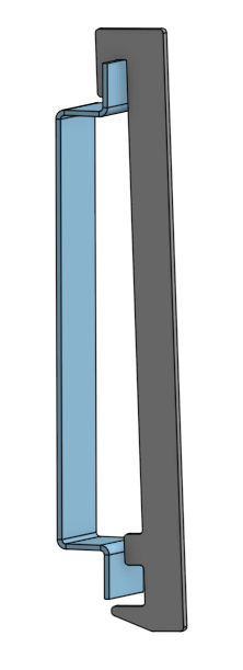
I need to mate a hook to a rail in an assembly. The hook touches the rail with three line contacts and has no flat surfaces that are parallel to the rail.
How can I mate the hook to the rail simulating the three line contacts?


Link to the assembly (in this simplified document the hook is constraint correctly to the rail in a sketch in the part studio, in real life the parts in the assembly are linked to different documents)


How can I mate the hook to the rail simulating the three line contacts?


Link to the assembly (in this simplified document the hook is constraint correctly to the rail in a sketch in the part studio, in real life the parts in the assembly are linked to different documents)


0
Comments
Would this work?
https://cad.onshape.com/documents/0cdba4db01184f17ae54bfa9/w/5cd90777edf69fa60da0d16f/e/4106905ce4371080ab48b4c5
Good use of a mate connector in part studio!
That does work in my public demo document, in reality the parts are not in the same part studio but are imported from different documents.
I need a way to mate the two parts in such a way that the correct position of the hook is a result of the mates in the assembly.
then I set a planar mate to the center of each part, so it's mated on center of the blue part
then add a tangent mate to each of the touching surfaces.
Use a vertex/surface when possible (my first mate in the gif)
then use line/surfaces as a secondary option
then use surface/surface as a last resort
this animation still took 3 recordings to show it working the first time... Tangent mates suck. They do in all 3D cad. But understanding they 'may break' is part of assemblies in any software. So, use the mate connector in the part studio first, but if you absolutely need to, then use the method I show as a second best.
even in the animation, you can see the second tangent mate did not work properly until I dragged the part closer to the edge. . . I hate tangent...
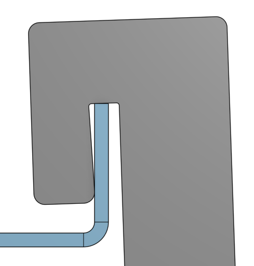
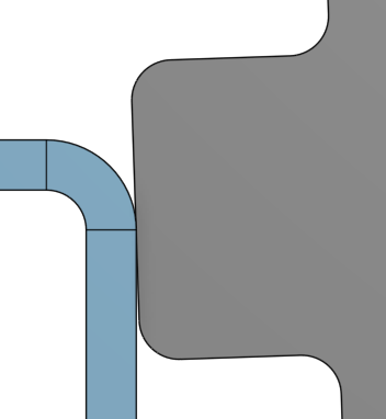
Thanks for your clear instructions. I tried the tangent mates before posting on the forum, but didn't succeed. Moving parts close to the correct position does help a lot. I think your 3rd mate is not mechanical right. In reality the hook will touch the face of the bend, not the tangent edge of the bend.
There is some interference now:
In this use case the error is neglegible and I can leave it at this.
We have this assembly also in Solidworks, and there I had the same issue, almost correct, but always a slight interference at that 3rd mate.
If however the bend on the rail were more then 90° the error would be too large to neglect.
I think that the tangent mate in Onshape might work a lot easier and be more robust if one could select specific faces to mate and not the entire circumference of the part.
So, i suppose we could trick with offset surfaces
Public file: hook&rail - Copy | dummy assy rail&hook (onshape.com)
go to your part studio, add a 0mm offset to the surfaces shown
insert and mate those surfaces to the parts
then use the surfaces as tangent selections
Works perfect:
I think this demonstrates that individual selectable surfaces would make the tangent mate much more usable.
Maybe there should be a uihint to toggle tanget connected surface or single surface next to each tanget mate selection
Good use of a mate connector in part studio!
That does work in my public demo document, in reality the parts are not in the same part studio but are imported from different documents.
I need a way to mate the two parts in such a way that the correct position of the hook is a result of the mates in the assembly.
Do you have enough symmetry or similarity between parts to do the math to place some mate connectors or can you use in-context? Maybe there are too many variables for that to work I'm not sure what you are dealing with, I have found that if you don't need motion then it is far faster and easier if you can just use a fasten mate.
Calculating the correct position and orientation of the mate connector is possible, but requires quite some work.
I think that your first suggestion of placing the mate connector in the part studio is faster, I can sketch and extrude a simplified model with only the relevant geometry of the rail in the part studio of the hook. Tangent constraints in the sketch are much easier than in the assembly.
Using one single mate connector is faster and more robust then using 3 tangent mates on added surfaces. Both approaches are viable and have their own merrits.