Welcome to the Onshape forum! Ask questions and join in the discussions about everything Onshape.
First time visiting? Here are some places to start:- Looking for a certain topic? Check out the categories filter or use Search (upper right).
- Need support? Ask a question to our Community Support category.
- Please submit support tickets for bugs but you can request improvements in the Product Feedback category.
- Be respectful, on topic and if you see a problem, Flag it.
If you would like to contact our Community Manager personally, feel free to send a private message or an email.
How to transition from a gear/shaft to a solid like a CNC milling bit would do
 brokk_galea
Member Posts: 8 ✭


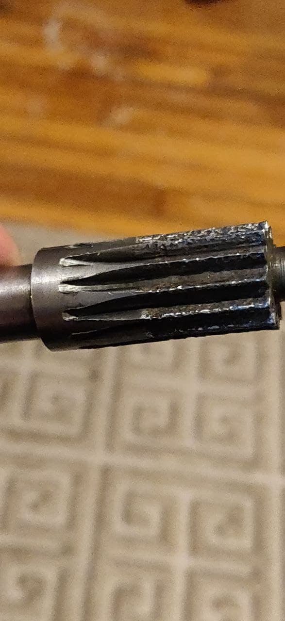
I have a pinion gear/shaft that is damaged and needs replacing. I would like to submit it to a machine shop via a CAD file. So I'm doing my best to try and reproduce this physical piece. The gear section is easy. The solid section at the other end is easy. Transitioning from one to the other is stumping me. I used "loft" and it did a great job guessing at how the transition is made. However, it spread out the valley as it it got more shallow, rather than narrowing the valley/groove as it does on this part.
https://cad.onshape.com/documents/cf8ea790a969c45e7997e086/v/763525e78ee0864db6cc9b20/e/ade32f6170dc8b5469c7c6bf
What is the best way to go about creating that transition?
I started with a 2D rendition of the gear in a DXF file, in case that makes a difference to the advice.
I also welcome any other advice that would help the final product to be more CNC friendly.
0
Best Answers
-
 S1mon
Member Posts: 3,989 PRO
They’re likely to be cutting this with dedicated gear cutters, so you only need to be so perfect with your 3D. Assuming you have the teeth cut to a blind depth, you just need to do a revolve/cut of the bottom face. Loft is not necessary.
Simon Gatrall | Product Development, Engineering, Design, Onshape | Ex- IDEO, PCH, Unagi, Carbon | LinkedIn
0 -
 NeilCooke
Moderator, Onshape Employees Posts: 5,971
  I used a custom feature. If you make a copy of the doc you can edit the feature to be whatever gear size you want.Senior Director, Technical Services, EMEA0
Answers
Simon Gatrall | Product Development, Engineering, Design, Onshape | Ex- IDEO, PCH, Unagi, Carbon | LinkedIn
You are basically suggesting rather than diagraming the cutter removing extra material as it completes the pass, I should just remove all the material from the path so the cutter won't have anything to hit? That does simplify the CAD drawing.
I'm not sure why the machinist who made this part previously chose the way he did it. Perhaps he was just being lazy. Looking at the gears from other posts for the same model out there, none of them were designed like the one I have.
Wow, that looks fantastic. But what techniques did you use to make that? My son (who knows CAD much better than me) struggled with a few things and couldn't get anywhere near as close as that.
I was just coming back here because the next one I'm drawing up has the same need, but this one has a gear pressed onto that portion of the shaft and it's phenolic material, so I would rather not make the shaft any narrower. Thus I would need to draw out a transition like that.
https://cad.onshape.com/documents/4dc6ead4d97d340b733fbc7c/w/20836c14ee57a3e8864f8100/e/0744a16a1ffa0921a4f15933
(I had to do something funky with "New" and "Boolean" to get the pattern to work.)
Just copy the document and you can edit the document.
How did you come up with the profile of the V? I started with a gear generator for my attempt, because I wasn't confident that I could draw the shape properly with the right dimensions. Perhaps I was getting hung up on the details. When I give this to a machine shop, so I just tell them what the gear is and the blind depth? The profile would be relatively standard, especially if they have a dedicated gear making process.
I'll be honest, I haven't had a lot of luck in editing my own CAD drawings. Most times it has seemed easier to just start over and redraw the items. Faster at least. So I'm a little nervous about trying to just edit yours for my purposes, without understanding how you built it.
The teeth aren't right for what I need (12 teeth, 20 dp, 14.5 pitch), so I would also need to draw it from scratch (I think).
I do understand about the revolve. I had to look it up after your first post.
You have the broken piece in your hands and with a simple caliper you can take measures from the broken part.