Welcome to the Onshape forum! Ask questions and join in the discussions about everything Onshape.
First time visiting? Here are some places to start:- Looking for a certain topic? Check out the categories filter or use Search (upper right).
- Need support? Ask a question to our Community Support category.
- Please submit support tickets for bugs but you can request improvements in the Product Feedback category.
- Be respectful, on topic and if you see a problem, Flag it.
If you would like to contact our Community Manager personally, feel free to send a private message or an email.
[FeatureScript] Creating randomized voids in order to strengthen 3D prints
 kenn_sebesta167
Member Posts: 113 ✭✭
kenn_sebesta167
Member Posts: 113 ✭✭
Inspired by https://reprapltd.com/fibre/, I made a FeatureScript which does something similar:
https://cad.onshape.com/documents/b95216af1e90e786deb23796/w/2ecd2d07e99b4ff6ba9897e3/e/13de5bd86cc0b577c88d0f8c
The idea is that a user could draw a volume inside a 3D print and use this to strengthen that volume.
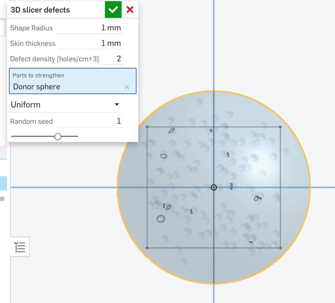
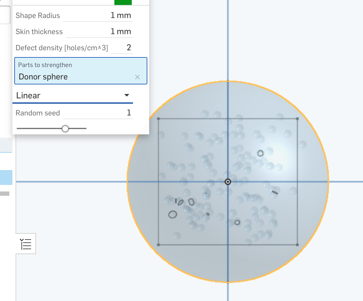
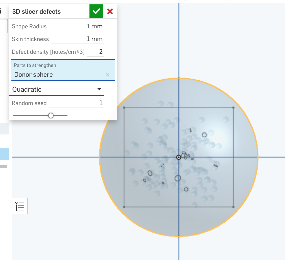
Users can choose to have the defects be uniformly distributed, to decay linearly toward the volume boundaries, or to decay quadratically toward the boundaries.
I used spheres instead of cylinders, as my logic is that the goal is to make a stronger isotropic material, whereas the cylinders as proposed in the original lead themselves more to anisotropic improvements. But if they are for anisotropic enhancement, then why choose random orientations? Seems like spheres are a more natural fit.
CAVEAT: This makes the STL file huge, like in some cases >100MB. However, once the file is imported the slicer hardly takes any longer to process it, and the gcode isn't much larger. I'm open to suggestions for how to reduce the STL file size. Perhaps cubes might be friendlier than spheres?
My first script, I'm curious for feedback. Took me gawdawful forever, but a lot of that was just learning the ropes.
https://cad.onshape.com/documents/b95216af1e90e786deb23796/w/2ecd2d07e99b4ff6ba9897e3/e/13de5bd86cc0b577c88d0f8c
The idea is that a user could draw a volume inside a 3D print and use this to strengthen that volume.
Users can choose to have the defects be uniformly distributed, to decay linearly toward the volume boundaries, or to decay quadratically toward the boundaries.
Uniform distribution:
Linear decay:
Quadratic decay:
I used spheres instead of cylinders, as my logic is that the goal is to make a stronger isotropic material, whereas the cylinders as proposed in the original lead themselves more to anisotropic improvements. But if they are for anisotropic enhancement, then why choose random orientations? Seems like spheres are a more natural fit.
CAVEAT: This makes the STL file huge, like in some cases >100MB. However, once the file is imported the slicer hardly takes any longer to process it, and the gcode isn't much larger. I'm open to suggestions for how to reduce the STL file size. Perhaps cubes might be friendlier than spheres?
My first script, I'm curious for feedback. Took me gawdawful forever, but a lot of that was just learning the ropes.
Tagged:
1
Comments
The Onsherpa | Reach peak Onshape productivity
www.theonsherpa.com
Will it break things badly for me to rename it and/or move it to another directory?
Now that I've given it a look and read the blog post you referenced I think I see why he chose cylinders instead of spheres. He was referencing composite fibers like carbon fiber and fiber glass (or old bricks made of clay and straw). You may already know all of this, but composite materials like that use long straight fibers (glass, carbon, or straw) which can take a lot of compression, but are too flexible on their own, and add a substrate that binds them together keeps them from bending (like resin or clay). I don't have a good guess whether that analogy actually translates to his 3D prints, or if the little holes just compel the slicer to add more material which makes it stronger no matter what the shape is. I'd say at least the second if not both. If you're up for running a test to see, I'd absolutely read a report of the findings 🤓
I'm always keeping an eye out for 3D printing related features so thanks for sharing yours.
The Onsherpa | Reach peak Onshape productivity
www.theonsherpa.com
Of course, for those same purposes it makes just as little sense to have spheres in the core. Instead, the advantage of having improved core material is better core crush resistance, which is a failure mode for transversally loaded composite beams. The improved core also provides strength for loadings in unanticipated directions.
It occurs to me that a future version of this could provide a "composite" reinforcement option, where the particle density decays from a maximum at the skin to 0 at the shear line. In my mind that's a lot harder, though, since it requires some way to handle the load direction.
Our printers are freeing up at the end of the week, we should be able to print a bunch of test coupons and see what real-world benefits, if any, this featurescript has.
I've found this guide very helpful over the years for strength estimates as a product of layer direction:
Example images available at https://icesl.loria.fr/pages/features/tetrahedral-infills/