Welcome to the Onshape forum! Ask questions and join in the discussions about everything Onshape.
First time visiting? Here are some places to start:- Looking for a certain topic? Check out the categories filter or use Search (upper right).
- Need support? Ask a question to our Community Support category.
- Please submit support tickets for bugs but you can request improvements in the Product Feedback category.
- Be respectful, on topic and if you see a problem, Flag it.
If you would like to contact our Community Manager personally, feel free to send a private message or an email.
How can I use perimeter as a constraint?
 jack_ellis462
Member Posts: 5 EDU
in Drawings
disclaimer: I know it isn't completely necessary to constrain with a perimeter in this particular project but I want to learn how to anyway.
I am working on a project that contains a chain and I am using the "curve pattern" tool in order to duplicate my chain across a path.
my problem is that If the perimeter of the path the chain follows isn't exactly a multiple of the pitch of the chain it won't link nicely.
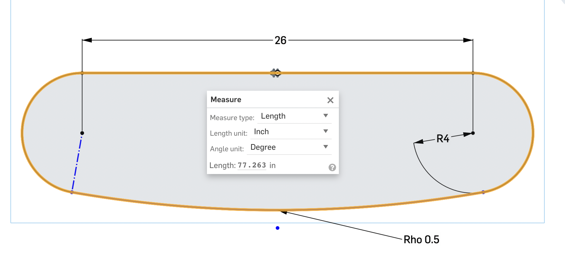
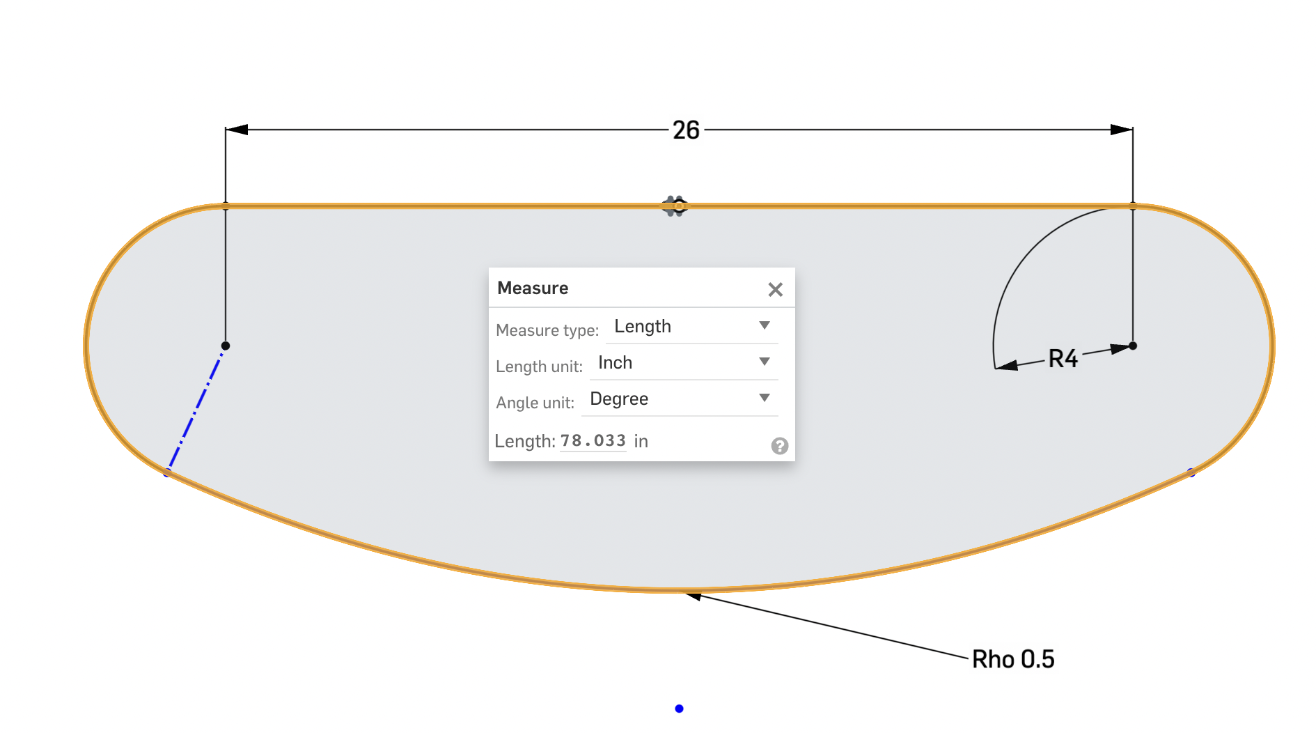
as shown in the photos below, the perimeter of the shapes changes as the center of the (hyperbola) changes. in most cases, I can just do some algebra to find what the lengths can be. in this project though I have no clue how to find the length of a segment of a hyperbola. and what angle the circle cuts off at.
I hope someone with better knowledge of constraints or hyperbolas can help me out.


0
Best Answers
-
 steve_shubin
Member Posts: 1,118 ✭✭✭✭
@jack_ellis462
https://cad.onshape.com/documents/2da3b19ff17770527f407de2/w/7107df2163263c5ecaf08a1f/e/1b34cb68fb6834bb13e3b31dSo it sounds like you’re really interested in the math. @mahir is probably the best person to help you on that.
But in the meantime, take a look at the different settings @imants_smidchens Chain Path featurescript gives you
In the document above, all the curves in the sketch are round
Here is the fearurescript1 -
 matthew_stacy
Member Posts: 489 PRO
@jack_ellis462 , this is a great topic that you raise. Onshape has many strengths, but making perimeter a driving parameter is not one of them. I did come up with a work-around for your consideration.Note that I simplified your use case to focus on the core functionality of your inquiry. I completely omitted the chain sag shown in your original sketches, because determining that catenary shape is non trivial. Instead, my example addresses chain-line geometry for a pair of sprockets and a specified length of chain (number of links of specified pitch). I made no provisions to account for slack (holler if you want to dive deeper on that one, several options come to mind).The trick is to create external variables for the LENGTH of all individual sketch elements comprising the perimeter, with the exception of the final segment (its length is driven). Number of chain links and chain pitch are driving variables (perimeter equal to the product thereof).Sprocket diameters are useful for initial setup, but must subsequently be toggled to DRIVEN dimensions. These are complemented by the associated arc lengths, which must are initially DRIVEN and then toggled to DRIVING dimensions.The remaining line segments (unsupported chain span) are constrained equal to one another. The sum of these span lengths is equal to the PERIMETER (product of links and pitch), less the wrapped arc lengths. This is reflected in the dimension formula in the sketch for that dimension.
 Edit the variables for number of links (#n) or pitch (#pitch) to drive the sketch. Total chain length (a.k.a perimeter) will update in the sketch.This task is much easier on other CAD platforms (e.g. SW) where every parameter is readily addressable by a default name (e.g. d1@sketch1) for use in equations. In Onshape we have to manually externalize those dimensional parameters in addition to toggling specific values back and forth between DRIVING / DRIVEN states, and verify that initial design intent was not lost (sprocket radius in this case). This is an iterative manual process.0
Answers
https://cad.onshape.com/documents/2da3b19ff17770527f407de2/w/7107df2163263c5ecaf08a1f/e/1b34cb68fb6834bb13e3b31d
But in the meantime, take a look at the different settings @imants_smidchens Chain Path featurescript gives you
In the document above, all the curves in the sketch are round
Here is the fearurescript
https://cad.onshape.com/documents/1be886df2e36b431c92b2d61/w/791200d47653055fd5d51eb7/e/17a1b8e5fd0b4440efc1c3de
Meansure Value Is a good feature for any measurement to variable you need
generates linearly spaced chain links (from basically any standard you would likely use, or a custom link type) with full control for arbitrarily many sprockets in any locations, including as tensioners.
Ping me if u need help or have suggestions!
imants.smidchens@gmail.com
https://cad.onshape.com/documents/2da3b19ff17770527f407de2/w/7107df2163263c5ecaf08a1f/e/296b742552b5807923deaa5e
Now I could be wrong, but I don’t think you’re going to get accuracy in using ONE curve pattern feature for the entire loop
When I tried Curve Pattern on this loop, it went off track on the tighter radius.
You could divide up a closed path into sections, such as the straight section, the arc of a cog, the arc along the sag. And then pattern each and connect the patterns with links. Then adjust the length or distance of some portion of that closed loop so that all the links connect to make a closed loop
With regards to sag, I’m guessing that the difference between catenary and an arc, is probably not going to make a significant difference in your case. So I’m going to go with the easier, and use an arc for sag.
The one thing with catenary in this case is, it probably would hang down a LITTLE bit lower. So if clearance was an issue, then you could take that into consideration
Here’s how I used @imants_smidchens chain path featurescript, and the measured value featurescript as @john_mcclary suggested, in order to make a chain loop
To do a chain loop takes three features
Sketch
Measured value
Chain path
In setting up the sketch, the origin is at the center of the 2 cogs. I made everything symmetric. And everything is tangent. And because everything is tangent you don’t have to worry about arc length of the cogs. You let the program figure that out for you
Now select the chain path fs
Set — How to cover up errors
To — Don’t cover gap
Apply the chain feature to the path in order to determine pitch for the chain size you have selected
Once you see the chain, select two adjacent rollers. You’ll be able to see their parallel axes distance down in the lower right. That’s your chain pitch
Knowing pitch, you can now determine a path length to use
Initially upon applying the chain path feature script, you’re most likely going to find a gap or an odd shaped link or a missing link. This means you have to make some adjustments
Within the sketch, you could adjust any part of the path you choose. It could be size of the sprockets, or the distance between, or the amount of sag.
I selected sag to adjust. Every time I changed the arc length, I kept an eye on measured value until I saw 78. This took about six tries to hit 78 right on the nose
On a chain that had a pitch of .625, I tried 78.125 for the path. And that was supposed to give me 125 links. But that didn’t work. So I had to deduct one link. I tried 124 links x .625 which gave me 77.5 and that worked
So you may have to either deduct or add one link if your path length does not work
I’m starting to wonder if you have to have an even number of links.
In another case I was using a chain that had pitch of .5 on a path of 78, and that worked fine. So I decided to use a chain that had twice the pitch — a pitch of 1 inch, and I did not have to change the path length at all. The 78 worked perfectly
The final way to tell if you’ve had success is by making a visual inspection. Any abnormal or missing links means you still have adjustments to make
In the document above, there’s four part studios where you can examine the feature settings. Each Part Studio has a different size chain. And all chains have ends that come together as they should